
Datasheet
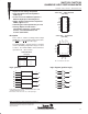

54ACT11000, 74ACT11000
QUADRUPLE 2-INPUT POSITIVE-NAND GATES
SCAS002A – D2957, JUNE 1987 – REVISED APRIL 1993
POST OFFICE BOX 655303 • DALLAS, TEXAS 75265
2–3
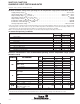
switching characteristics over recommended ranges of supply voltage and free-air temperature
(unless otherwise noted) (see Figure 1)
PARAMETER
FROM TO
T
A
= 25°C 54ACT11000 74ACT11000
UNIT
PARAMETER
(INPUT) (OUTPUT)
MIN TYP MAX MIN MAX MIN MAX
UNIT
t
PLH
AorB
Y
1.5 7.2 10.9 1.5 13.3 1.5 12.3
ns
t
PHL
A
or
B
Y
1.5 5.8 8 1.5 9.5 1.5 8.8
ns
operating characteristics, V
CC
= 5 V, T
A
= 25°C
PARAMETER TEST CONDITIONS TYP UNIT
C
pd
Power dissipation capacitance per gate C
L
= 50 pF, f = 1 MHz 23 pF
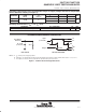
PARAMETER MEASUREMENT INFORMATION
VOLTAGE WAVEFORMS
LOAD CIRCUIT
Input
(see Note B)
1.5 V 1.5 V
50% V
CC
50% V
CC
t
PHL
t
PLH
3 V
Output
V
OL
V
OH
0 V
From Output
Under Test
C
L
= 50 pF
(see Note A)
500 Ω
NOTES: A. C
L
includes probe and jig capacitance.
B. Input pulses are supplied by generators having the following characteristics: PRR ≤ 10 MHz, Z
O
= 50 Ω, t
r
= 3 ns, t
f
= 3 ns.
C. The outputs are measured one at a time with one input transition per measurement.
Figure 1. Load Circuit and Voltage Waveforms