
Datasheet
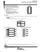


74ACT11008
QUADRUPLE 2-INPUT POSITIVE-AND GATE
SCAS013C – AUGUST 1987 – REVISED APRIL 1996
3
POST OFFICE BOX 655303 • DALLAS, TEXAS 75265
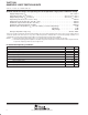
electrical characteristics over recommended operating free-air temperature range (unless
otherwise noted)
PARAMETER
TEST CONDITIONS
V
CC
T
A
= 25°C
MIN
MAX
UNIT
PARAMETER
TEST
CONDITIONS
V
CC
MIN TYP MAX
MIN
MAX
UNIT
I
OH
=50A
4.5 V 4.4 4.4
V
OH
I
OH
= –
50
A
5.5 V 5.4 5.4
V
V
OH
I
OH
=24mA
4.5 V 3.94 3.7
V
I
OH
= –
24
mA
5.5 V 4.94 4.7
I
OL
=50 A
4.5 V 0.1 0.1
V
OL
I
OL
=
50
A
5.5 V 0.1 0.1
V
V
OL
I
OL
=24mA
4.5 V 0.36 0.44
V
I
OL
=
24
mA
5.5 V 0.36 0.44
I
OH
†
V
O
= 3.85 V 5.5 V –75 mA
I
OL
†
V
O
= 1.65 V 5.5 V 75 mA
I
I
V
I
= V
CC
or GND 5.5 V ±0.1 ±1 A
I
CC
V
I
= V
CC
or GND, I
O
= 0 5.5 V 4 40 A
I
CC
‡
One input at 3.4 V,
55V
09
1
mA
I
CC
‡
,
Other inputs at GND or V
CC
5
.
5
V
0
.
9
1
mA
C
i
V
I
= V
CC
or GND 5 V 3.5 pF
†
Not more than one output should be tested at a time, and the duration of the test should not exceed 1 second.
‡
This is the increase in supply current for each input that is at one of the specified TTL voltage levels rather than 0 or V
CC
.
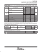
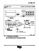
switching characteristics over recommended ranges of supply voltage and free-air temperature
(unless otherwise noted) (see Figure 1)
PARAMETER
FROM TO
T
A
= 25°C
MIN
MAX
UNIT
PARAMETER
(INPUT) (OUTPUT)
MIN TYP MAX
MIN
MAX
UNIT
t
PLH
AorB
Y
1.5 5.8 8 1.5 9
ns
t
PHL
A
or
B
Y
1.5 5.2 7.7 1.5 8.2
ns
operating characteristics, V
CC
= 5 V, T
A
= 25°C
PARAMETER TEST CONDITIONS TYP UNIT
C
pd
Power dissipation capacitance per gate C
L
= 50 pF, f = 1 MHz 29 pF