
Datasheet


®
ACF2101
3
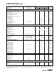
SPECIFICATIONS (CONT)
At T
A
= +25°C, V+ = +5V, V– = –15V, Internal C
INTEGRATION
= C
INTERNAL
= 100pF, unless otherwise noted.
ACF2101BP, BU
PARAMETER CONDITIONS MIN TYP MAX UNITS
OUTPUT
Voltage Output Range (All Outputs) –10 –13.5, +1.0 +0.5 V
Current Output, Direct Output (Out A, Out B) ±5mA
Short Circuit Current
Direct Output ±25 mA
Switched Output (Sw Out A, Sw Out B) ±2 ±8mA
Select Switch Withstand Voltage
Switched Output –10 +0.5 V
Switched Common (Sw Com A, Sw Com B) –0.5 +0.5 V
Output Impedance
Direct Output 0.1 Ω
Switched Output
Select Switch ON 250 || 5 Ω || pF
Select Switch OFF 1000 || 4 GΩ || pF
Leakage Current Select Switch OFF 10 100 pA
Load Capacitance Stability
Direct Output 500 pF
Switched Output Any pF
OUTPUT ACCURACY
Nonlinearity ±0.005 ±0.01 %FSR
Channel Separation –80 dB
Op Amp Bias Current
Value 100 1000 fA
Temperature Coefficient Doubles Each +10°C
Hold Mode Droop 1 10 nV/µs
Integrate Mode Droop 1 10 nV/µs
Voltage Offset
(2)
Value 3mV
Temperature Coefficient 5 µV/°C
Power Supply Rejection V
S
= +4.5V to +18V, –10V to –18V 80 100 dB
OUTPUT NOISE
Total Output Noise
(3)
BW = 0.1Hz to 10Hz 2 µVrms
Integrate Mode
(4)
BW = 0.1Hz to 250kHz 10(1 + C
IN
/C
INTEGRATION
) µVrms
Hold Mode BW = 0.1Hz to 250kHz 10 µVrms
Reset Mode BW = 0.1Hz to 250kHz 10 µVrms
CHARGE TRANSFER ERRORS
(5)
Reset to Integrate Mode
(6)
Charge Transfer 0.1 0.5 pC
Charge Transfer TC 0.2 fC/°C
Charge Offset Error 15mV
Charge Offset TC 2 µV/°C
Integrate to Hold Mode C
IN
> 50pF
Charge Transfer 0.2 1 pC
Charge Transfer TC 0.4 fC/°C
Charge Offset Error 210mV
Charge Offset TC 4 µV/°C
Hold to Integrate Mode C
IN
> 50pF
Charge Transfer 0.2 1 pC
Charge Transfer TC 0.4 fC/°C
Charge Offset Error 210mV
Charge Offset TC 4 µV/°C
POWER SUPPLY
Specified Operating Voltage +5, –15 V
Operating Voltage Range
Positive Supply +4.5 +18 V
Negative Supply –10 –18 V
Current
Positive Supply For Dual 12 15 mA
Negative Supply For Dual 3.5 5.2 mA
TEMPERATURE RANGE
Specification –40 +85 °C
Operation –40 +125 °C
Storage –40 +125 °C
Thermal Resistance (both packages) Junction to Ambient 100 °C/W
NOTES: (1) FSR is Full Scale Range = 10V (0 to –10V). (2) Includes offset errors from all modes of operation. (3) Total noise is rms total of noise for the modes
of operation used. (4) C
IN
= capacitance of sensor connected to ACF2101 input; C
INTERGRATION
= integration capacitance = C
INTERNAL
+ C
EXTERNAL
. (5) Errors created
when the internal switches are driven from one mode to another. (6) The charge transfer is 0.1pC; for an integration capacitance of 100pF, the resultant charge
offset voltage error is 1mV.