
Datasheet


®
ACF2101
8
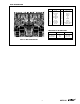
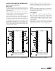
FIGURE 1c. Circuit Connections with External Capacitors
and Guarding, SOIC package.
FIGURE 1d. Circuit Connections with External Capacitors
and Guarding, DIP.
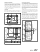
FIGURE 2b. PC Board Layout Showing “Guard” Traces for
Input, DIP. Both top and bottom of board
should be guarded.
FIGURE 2a. PC Board Layout Showing “Guard” Traces for
Input, SOIC package. Both top and bottom of
board should be guarded.
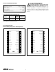
Top View ACF2101BU Top View ACF2101BP
ACF2101BU ACF2101BP
Guards
Sw In A 24
In A 23
Cap A 22
Com A 21
1 Sw In B
2 In B
3 Cap B
4 Com B
SOIC
Guards
3 Com A
4 Cap A
5 In A
6 Sw In A
7 Sw In B
8 In B
9 Cap B
10 Com B
DIP
Sw In B
In B
Cap B
Com B
Gnd B
Out B
V–
Sw In A
In A
Cap A
Com A
Gnd A
Out A
V+
1
2
3
4
5
6
7
8
9
10
11
12
24
23
22
21
20
19
18
17
16
15
14
13
1µF
V–
1µF
V+
Input Input
* Optional External C
Guards
These points must be connected to a
common ground point or a ground plane.
++
V
OUT
*
*
V
OUT
SOIC
Out A
Gnd A
Com A
Cap A
In A
Sw In A
Sw In B
In B
Cap B
Com B
Gnd B
Out B
V+
V–
1
2
3
4
5
6
7
8
9
10
11
12
24
23
22
21
20
19
18
17
16
15
14
13
Input
Optional External C
Guards
These points must be connected to a
common ground point or a ground plane.
*
V
OUT
Input
V
OUT
*
*
DIP
V+
V–
1µF
1µF