
User's Manual
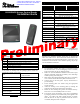
Determining Which Wires Will Be Used
The following wire connections are essential for proper
functionality in RS-485 or Wiegand mode.
Wiegand Mode RS-485 Mode
Black Ground Black Ground
Red Power Red Power
Green Data (0) Gray Data (A or -)
White Data (1) Violet Data (B or +)
The remaining wires may be connected as desired to customize
functionality of the audio and LED indicators. See the S6400
User’s Guide (11-06-21-711) for more information regarding the
use of these wires.
Complete Wire Guide
Color Function
Black Ground (GND)
Red Power (9-14 VDC)
Gray RS-485(A or -)
Violet RS-485(B or +)
Green Wiegand Data(0)
White Wiegand Data(1)
Brown Red LED
Orange Green LED
Yellow Audio
Blue Hold
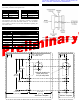
Mounting
Note: Optimum read range can be achieved by pushing excess
wire through opening in wall. Wire accumulated inside reader
housing may cause read range to diminish.
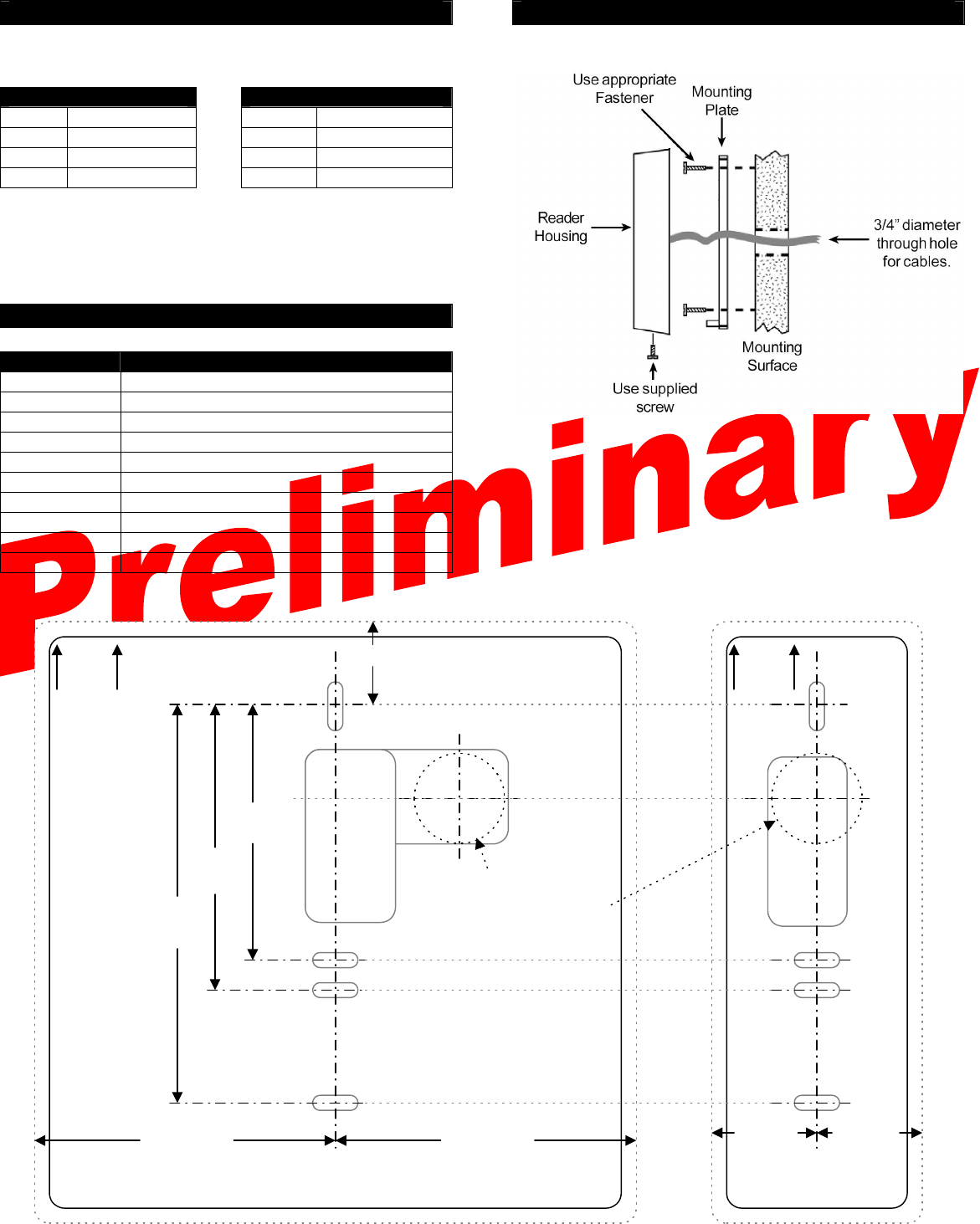
UP UP
3 5/16"
(84 mm)
Optimum location for
cable entry hole.
3/4" (20 mm) MAX
2 1/8"
(54 mm)
2 3/8"
(60 mm)
Allow 1" (25 mm) min.
for reader cover
Wall Plate Template Mullion Template
2 1/2" min.
(63 mm)
2 1/2" min.
(63 mm)
7/8" min.
(22 mm)
7/8" min.
(22 mm)
* Information submitted for FCC, Industry Canada, RTTE, CE
& ETL certification: A92ACS6410, A92ACS6420 *