
User's Manual
11-06-21-713 09/02
Packing List
This package includes:
Qty. Description
1 S6410 or S6420 Reader with back plate
2 #6 Phillips-head machine mounting screws
2 #6 Phillips-head self-tapping mounting screws
1 Phillips-head cover screw
1 Security-head cover screw
1 Installation guide (this sheet)
If any items are missing from the package, please contact the
appropriate technical support agent:
USA
1-888-937-6536 or
1 (972)-575-4364
Belgium (English) +32 (0)2 7455455
France (English) +33 4 93 22 22 00
Germany +49 (0)8161 80 2200
Italy +39 (0)39 6568 210
Netherlands (English) +31 (0)546 879 222
Spain +34 902 19 73 96
Sweden (English) +46 (0)8 58755527
UK +44 (0)1604 88 4088
or visit us at: www.ti-rfid.com
Specifications
Reader Model S6410 Wall Plate S6420 Mullion
Part number RI-H4R-S6H3-00 RI-H4R-S5H3-00
Operating Frequency 13.56 MHz
Supported Protocols ISO/IEC 15693 (Vicinity)
Supply Voltage
9 - 14 VDC, built-in overvoltage
and reverse polarity protection
Power Consumption 90 mA Quiescent, 200 mA Read, 300 mA Max
RS-485 Baud Rates 9600, 19200, 38400 (Default)
Communication
Interface
Wiegand 26-64 bit and RS-485 protocol
Data Signal Integrity 500 feet Wiegand, 4000 feet RS-485
Data Output Format
DES Encryption Mode (Cyper Text),
Wiegand UID Mode, Wiegand ASCII mode
Operating Temperature
-20°C to +70°C
Storage Temperature -40°C to +85°C
Humidity 90% RH at 70°C
Protection Class IP64, Potted
Regulatory Approvals FCC, R&TTE (CE), UL-94 and UL-294 (ETL)
Overall Dimensions
5.0” x 5.0” x 1.0”
(12.7 x 12.7 x 2.5 cm)
5.0” x 1.7” x 1.0”
(12.7 x 4.3 x 2.5 cm)
Weight ~8.5 oz (~241 g) ~4.8 oz (~136 g)
Complete warranty information can be found on the website at:
www.ti-rfid.com
© Copyright Texas Instruments. 2002
All rights reserved.
Before You Begin
Determine the installation method, which parts are needed, and
which wires will be used. These instructions assume that the unit
is being installed on an unprepared flat surface. If this unit is to be
installed in an electrical box or door mullion opening, skip to step
3 of the installation instructions.
Typical Installation
1. Use appropriate template (from back) to mark hole locations
for wire and screws. A set of self-tapping screws is included,
however the holes may be pre-drilled if desired.
2. Drill a 3/4” (20 mm) maximum diameter hole for wire to pass
through. Placement of this hole is arbitrary, but it must align
with the opening of the back plate.
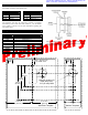
3. Slide wiring cable through mounting plate prior to connecting
wires. Be sure the flat side of the plate is toward the wall.
4. Connect wires per the wire guide. Cap any unused wires to
prevent shorting.
5. Screw mounting plate onto surface using the appropriate
screws provided.
6. Attach the housing to the mounting plate by inserting the
upper tab(s) of the housing into the slots in the plate.
7. Secure the front housing using either the included security-
head cover screw or the Phillips-head cover screw.
8. Test unit for proper functionality. This can be accomplished
by bringing a card into the read field with power applied to the
reader. The LED’s and audio should function as desired.
Note that this test can only be performed when the unit is in
it’s default (Wiegand) mode as shipped.
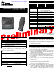
S6410/S6420 Access Control Reader
Installation Guide
* Information submitted for FCC, Industry
Canada, RTTE, CE & ETL certification:
A92ACS6410 &A92ACS6420 *