
Datasheet

ADC08060
SNAS120H –OCTOBER 2000–REVISED MARCH 2013
www.ti.com
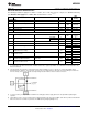
Absolute Maximum Ratings
(1)(2)(3)
Supply Voltage (V
A
) 3.8V
Driver Supply Voltage (DR V
D
) V
A
+ 0.3V
Voltage on Any Input or Output Pin −0.3V to V
A
Reference Voltage (V
RT
, V
RB
) V
A
to AGND
CLK, OE Voltage Range −0.3V to
(V
A
+ 0.3V)
Digital Output Voltage (V
OH
, V
OL
) DR GND to DR V
D
Input Current at Any Pin
(4)
±25 mA
Package Input Current
(4)
±50 mA
Power Dissipation at T
A
= 25°C See
(5)
ESD Susceptibility
(6)
Human Body Model 2500V
Machine Model 250V
Soldering Temperature, Infrared, 10 seconds
(7)
235°C
Storage Temperature −65°C to +150°C
(1) All voltages are measured with respect to GND = AGND = DR GND = 0V, unless otherwise specified.
(2) Absolute Maximum Ratings indicate limits beyond which damage to the device may occur, including inoperability and degradation of
device reliability and/or performance. Functional operation of the device and/or non-degradation at the Absolute Maximum Ratings or
other conditions beyond those indicated in the Recommended Operating Conditions is not implied. The recommended Operating
Conditions indicate conditions at which the device is functional and the device should not be operated beyond such conditions.
(3) If Military/Aerospace specified devices are required, please contact the Texas Instruments Sales Office/ Distributors for availability and
specifications.
(4) When the input voltage at any pin exceeds the power supplies (that is, less than AGND or DR GND, or greater than V
A
or DR V
D
), the
current at that pin should be limited to 25 mA. The 50 mA maximum package input current rating limits the number of pins that can
safely exceed the power supplies with an input current of 25 mA to two.
(5) The absolute maximum junction temperature (T
J
max) for this device is 150°C. The maximum allowable power dissipation is dictated by
T
J
max, the junction-to-ambient thermal resistance (θ
JA
), and the ambient temperature (T
A
), and can be calculated using the formula
P
D
MAX = (T
J
max − T
A
) / θ
JA
. The values for maximum power dissipation will be reached only when this device is operated in a severe
fault condition (e.g., when input or output pins are driven beyond the power supply voltages, or the power supply polarity is reversed).
Obviously, such conditions should always be avoided.
(6) Human body model is 100 pF capacitor discharged through a 1.5 kΩ resistor. Machine model is 220 pF discharged through ZERO
Ohms.
(7) See AN-450, “Surface Mounting Methods and Their Effect on Product Reliability” ().
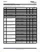
Operating Ratings
(1)(2)
Operating Temperature Range −40°C ≤ T
A
≤ +85°C
Supply Voltage (V
A
) +2.7V to +3.6V
Driver Supply Voltage (DR V
D
) +2.4V to V
A
Ground Difference |GND - DR GND| 0V to 300 mV
Upper Reference Voltage (V
RT
) 1.0V to (V
A
+ 0.1V)
Lower Reference Voltage (V
RB
) 0V to (V
RT
− 1.0V)
V
IN
Voltage Range V
RB
to V
RT
(1) Absolute Maximum Ratings indicate limits beyond which damage to the device may occur, including inoperability and degradation of
device reliability and/or performance. Functional operation of the device and/or non-degradation at the Absolute Maximum Ratings or
other conditions beyond those indicated in the Recommended Operating Conditions is not implied. The recommended Operating
Conditions indicate conditions at which the device is functional and the device should not be operated beyond such conditions.
(2) All voltages are measured with respect to GND = AGND = DR GND = 0V, unless otherwise specified.
4 Submit Documentation Feedback Copyright © 2000–2013, Texas Instruments Incorporated
Product Folder Links: ADC08060