
Datasheet

ADC0820-N
SNAS529C –JUNE 1999–REVISED MARCH 2013
www.ti.com
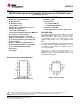
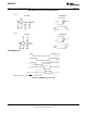
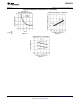
TRI-STATE Test Circuits and Waveforms
t
r
=20 ns
t
1H
Circuit t
1H
Waveform
t
r
=20 ns
t
0H
Circuit t
0H
Waveform
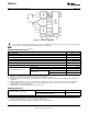
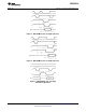
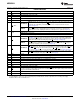
Timing Diagrams
Note: On power-up the state of INT can be high or low.
Figure 4. RD Mode (Pin 7 is Low)
6 Submit Documentation Feedback Copyright © 1999–2013, Texas Instruments Incorporated
Product Folder Links: ADC0820-N