
Datasheet


ADC0831-N, ADC0832-N, ADC0834-N, ADC0838-N
SNAS531B –AUGUST 1999–REVISED MARCH 2013
www.ti.com
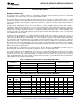
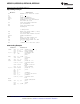
Table 3. MUX Addressing: ADC0838-N Differential MUX Mode
MUX Address Analog Differential Channel-Pair #
SGL/ ODD/ SELECT 0 1 2 3
DIF SIGN 1 0 0 1 2 3 4 5 6 7
0 0 0 0 + −
0 0 0 1 + −
0 0 1 0 + −
0 0 1 1 + −
0 1 0 0 − +
0 1 0 1 − +
0 1 1 0 − +
0 1 1 1 − +
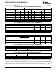
Table 4. MUX Addressing: ADC0834-N Single-Ended MUX Mode
MUX Address Channel #
SELECT
SGL / DIF ODD / SIGN 0 1 2 3
1
1 0 0 +
1 0 1 +
1 1 0 +
1 1 1 +
Table 5. MUX Addressing: ADC0834-N Differential MUX Mode
MUX Address Channel #
SELECT
SGL / DIF ODD / SIGN 0 1 2 3
1
0 0 0 + −
0 0 1 + −
0 1 0 − +
0 1 1 − +
Table 6. MUX Addressing: ADC0832-N Single-Ended MUX Mode
MUX Address Channel #
SGL / DIF ODD / SIGN 0 1
1 0 +
1 1 +
Table 7. MUX Addressing: ADC0832-N Differential MUX Mode
MUX Address Channel #
SGL / DIF ODD / SIGN 0 1
0 0 + −
0 1 − +
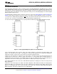
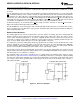
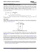
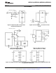
Since the input configuration is under software control, it can be modified, as required, at each conversion. A
channel can be treated as a single-ended, ground referenced input for one conversion; then it can be
reconfigured as part of a differential channel for another conversion. Figure 22 illustrates the input flexibility which
can be achieved.
The analog input voltages for each channel can range from 50 mV below ground to 50 mV above V
CC
(typically
5V) without degrading conversion accuracy.
14 Submit Documentation Feedback Copyright © 1999–2013, Texas Instruments Incorporated
Product Folder Links: ADC0831-N ADC0832-N ADC0834-N ADC0838-N