
Datasheet


ADC0831-N, ADC0832-N, ADC0834-N, ADC0838-N
www.ti.com
SNAS531B –AUGUST 1999–REVISED MARCH 2013
Functional Description
Multiplexer Addressing
The design of these converters utilizes a sample-data comparator structure which provides for a differential
analog input to be converted by a successive approximation routine.
The actual voltage converted is always the difference between an assigned “+” input terminal and a “−” input
terminal. The polarity of each input terminal of the pair being converted indicates which line the converter expects
to be the most positive. If the assigned “+” input is less than the “−” input the converter responds with an all zeros
output code.
A unique input multiplexing scheme has been utilized to provide multiple analog channels with software-
configurable single-ended, differential, or a new pseudo-differential option which will convert the difference
between the voltage at any analog input and a common terminal. The analog signal conditioning required in
transducer-based data acquisition systems is significantly simplified with this type of input flexibility. One
converter package can now handle ground referenced inputs and true differential inputs as well as signals with
some arbitrary reference voltage.
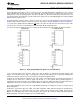
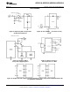
A particular input configuration is assigned during the MUX addressing sequence, prior to the start of a
conversion. The MUX address selects which of the analog inputs are to be enabled and whether this input is
single-ended or differential. In the differential case, it also assigns the polarity of the channels. Differential inputs
are restricted to adjacent channel pairs. For example channel 0 and channel 1 may be selected as a different
pair but channel 0 or 1 cannot act differentially with any other channel. In addition to selecting differential mode
the sign may also be selected. Channel 0 may be selected as the positive input and channel 1 as the negative
input or vice versa. This programmability is best illustrated by the MUX addressing codes shown in the following
tables for the various product options.
The MUX address is shifted into the converter via the DI line. Because the ADC0831-N contains only one
differential input channel with a fixed polarity assignment, it does not require addressing.
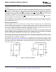
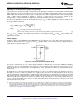
The common input line on the ADC0838-N can be used as a pseudo-differential input. In this mode, the voltage
on this pin is treated as the “−” input for any of the other input channels. This voltage does not have to be analog
ground; it can be any reference potential which is common to all of the inputs. This feature is most useful in
single-supply application where the analog circuitry may be biased up to a potential other than ground and the
output signals are all referred to this potential.
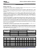
Table 1. Multiplexer/Package Options Single-Ended MUX Mode
Number of Analog Channels
Part Number Number of Package Pins
Single-Ended Differential
ADC0831-N 1 1 8
ADC0832-N 2 1 8
ADC0834-N 4 2 14
ADC0838-N 8 4 20
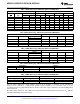
Table 2. MUX Addressing: ADC0838-N Single-Ended MUX Mode
MUX Address Analog Single-Ended Channel #
SGL/ ODD/ SELECT 0 1 2 3 4 5 6 7 COM
DIF SIGN 1 0
1 0 0 0 + −
1 0 0 1 + −
1 0 1 0 + −
1 0 1 1 + −
1 1 0 0 + −
1 1 0 1 + −
1 1 1 0 + −
1 1 1 1 + −
Copyright © 1999–2013, Texas Instruments Incorporated Submit Documentation Feedback 13
Product Folder Links: ADC0831-N ADC0832-N ADC0834-N ADC0838-N