
Datasheet

t
OD
Clock N Clock N + 7
Sample N + 7
t
AD
Sample N + 6
Sample N
Sample N + 8
Sample N + 9
Sample N + 10
CLK
V
IN
D0 - D11
t
CL
t
CH
Data N + 2
|
|
Data N - 1
1
f
CLK
Data N
Latency
Data N + 1
|
|
DRDY
|
t
H
t
SU
|
ADC12C105
SNAS417B –MAY 2007–REVISED AUGUST 2007
www.ti.com
SIGNAL TO NOISE RATIO (SNR) is the ratio, expressed in dB, of the rms value of the input signal to the rms
value of the sum of all other spectral components below one-half the sampling frequency, not including
harmonics or DC.
SIGNAL TO NOISE PLUS DISTORTION (S/N+D or SINAD) Is the ratio, expressed in dB, of the rms value of the
input signal to the rms value of all of the other spectral components below half the clock frequency, including
harmonics but excluding d.c.
SPURIOUS FREE DYNAMIC RANGE (SFDR) is the difference, expressed in dB, between the rms values of the
input signal and the peak spurious signal, where a spurious signal is any signal present in the output spectrum
that is not present at the input.
TOTAL HARMONIC DISTORTION (THD) is the ratio, expressed in dB, of the rms total of the first six harmonic
levels at the output to the level of the fundamental at the output. THD is calculated as
(3)
where f
1
is the RMS power of the fundamental (output) frequency and f
2
through f
7
are the RMS power of the first
six harmonic frequencies in the output spectrum.
SECOND HARMONIC DISTORTION (2ND HARM) is the difference expressed in dB, between the RMS power in
the input frequency at the output and the power in its 2nd harmonic level at the output.
THIRD HARMONIC DISTORTION (3RD HARM) is the difference, expressed in dB, between the RMS power in
the input frequency at the output and the power in its 3rd harmonic level at the output.
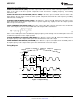
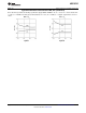
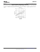
Timing Diagram
Figure 1. Output Timing
12 Submit Documentation Feedback Copyright © 2007, Texas Instruments Incorporated
Product Folder Links: ADC12C105