
Datasheet


ADC12EU050
WV5 Connector
Inputs
Input Clock circuitry
Hardware
Reset
Sleep
Power Connectors
Board Assembly
www.ti.com
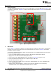
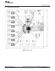
1 Board Assembly
The ADC12EU050 Evaluation Board comes pre-assembled. Refer to the Bill of Materials in Section 7 for a
description of components, to Figure 1 for major component placement and to Section 5 for the Evaluation
Board schematic.
Figure 1. Major Component Locations
2 Quick Start
Refer to Figure 1 for locations of jumpers, test points and major components. The board is configured by
default to use an on board crystal clock source and internal reference. Refer to Section 3 for detailed
information on jumper settings.
You must have the WaveVision5™ software to test this board. You can download the latest version from
the Texas Instruments website.
1. Connect the ADC12EU050 evaluation board to the WaveVision5™ Data Capture Board.
2. Apply power to the WaveVision5™ Data Capture Board.
3. Connect power to the ADC12EU050 board as described in Section 3.4, and power it up.
4. Connect the WaveVision5™ board to the computer using a USB cable.
5. Start the WaveVision5™ software.
6. Connect a signal from a 50-Ω source to connector a channel input. Be sure to use a bandpass filter
before the Evaluation Board.
7. Adjust the input signal amplitude as needed to ensure that the signal does not over-range by
examining an FFT of the output data with the WaveVision™ software.
2
ADC12EU050: Ultra-low Power, Octal, 12-bit, 45MSPS Sigma-Delta Analog- SNAU020–September 2013
to-Digital Converter
Submit Documentation Feedback
Copyright © 2013, Texas Instruments Incorporated