
Datasheet

- 33 -
Copyright 2011 National Semiconductor Corporation
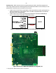
AutoSync SMA connectors: Needs resistor jumper modification to evaluate AutoSync on the
reference board. See schematic to find the resistor locations.
• Remove DCLKQ+/-, RCOUT1+/- to FPGA (Remove R162, R163, R158, R159)
• Route DCLKQ+/-, RCOUT1+/-, RCLK+/- to SMA connectors (Stuff 0ohm resistors to
R161, R164, R157, R160, R145, R147)
Enable AutoSync output by going to Wavevision 5 Software GUI -> Registers tab -> AutoSync
panel -> Uncheck DOC and click ‘Write AutoSync Reg’. Notice that LED RCOUT1/2_ENABLED
will light and DCLK_LOCKED will not light.
The board has SMA connectors for DCLKQ+, DCLKQ-, RCOUT1+, RCOUT1-, RCLK+, RCLK-
on the board. See the ADC12D1X00RF datasheet and Application Note 2132 for details on how
to use the AutoSync feature.
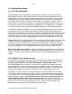
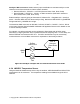
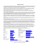
For example, one reference board can be configured in Slave Mode and its RCLK driven
externally by a signal generator which is phase locked to the sampling clock. For this setup, the
Reference Board must select the EXT CLK. The DCLK and RCOut1 may be conveniently
monitored via the on-board SMA connectors for exploration of the AutoSync feature.
Rclk
10MHz
Ref
SigGen
Fclk
SigGen
Rclk=Fclk/4
ADC in
Autosync
Slave Mode
Figure 21: AutoSync example with one reference board in slave mode
4.2.4 LM95233 Temperature Sensor
Using the National LM95233 temp sensor chip; the ambient, ADC12D1X00RF and Xilinx FPGA
temperatures can be monitored. The temperature readings are available through the WV-5
software.