
Datasheet

- 7 -
Copyright 2011 National Semiconductor Corporation
2.0 Quick Start
This section will aid in bringing up the board for the first time as well as a brief tutorial on the
WaveVision 5 (WV5) software. Further description of the Reference Board is in subsequent
sections of this document. The software is further described in the WaveVision 5 Users' Guide
or the HELP function within the software. The ADC12D1X00RF and LMX2531 datasheets
should be consulted for detailed understanding of device functionality.
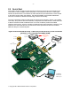
The user is advised to construct a lab setup as close to the one shown in Figure 3 as possible.
This setup, along with the board and software configuration described below, is what was used
to test the reference board at National's lab. This set of conditions produces the stated
reference performance - which is normally included with each board shipped to customers. The
objective is to assure that the user can achieve the same performance as that recorded at
National's lab prior to board shipment.
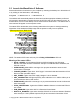
Figure 3: Recommended lab setup. A filter may not be necessary on the clock if the
generator is very clean (beyond -80dBm SFDR).
Attach only if
external clock source
desired
Computer
Windows XP
USB 2.0 port
+7.5V
adapter (supplied)
110-240V
AC Outlet
Low-noise
Signal Gen.
Low-noise
Signal Gen.
ADC12D1X00RFRB