
Datasheet

- 8 -
Copyright 2011 National Semiconductor Corporation
2.1 Installing the WaveVision 5 Software
(Note: The WaveVision 5 software requires Windows XP 32-bit operating system)
1. Insert the included WaveVision 5 CD-ROM into the computer CD drive.
2. Locate, unzip and run the install.bat program on the CD-ROM.
3. Follow the on-screen instructions to complete the installation.
2.2 Installing the ADC12D1X00RFRB Hardware
1. Place the ADC12D1X00RFRB Reference Board on a clean, static-free surface.
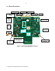
2. Make sure the board's jumpers are configured as follows as shown in Figure 2:
a. For the ADC, the "ECE (Extended Control Enable, active low)" jumper
should be installed in the LOW position. This enables SPI control of the
ADC.
b. Pin 9 on J15 must be connected to Ground for ac-coupled operation. The
board ships with this jumper in place as it is configured for ac-coupled
operation only. (The jumper is removed for dc-coupled operation. In that
case the applied signal must be dc-coupled, and have the common mode
DC voltage set to the required ADC12D1X00RF V
CM
voltage.)
c. The PDI and PDQ jumpers must be in place as shown to enable both
channels of the ADC.
3. Connect the enclosed +7.5V DC power adapter to the power jack. Connect the other
side of the power supply to an AC outlet (100-240 VAC, 50-60 Hz).
4. Connect the input signal generator, the band-pass filter, the balun and the DC blocks to
the ADC12D1X00RFRB Reference Board's I-channel input connectors. Set the signal
generator at one of the frequencies and signal levels stated in the reference
performance report. Always use high-quality RF SMA cables for optimum performance.
Do not overdrive the signal and clock inputs as the ADC may be damaged. Refer to
the Electrical Specification section of the datasheet for the voltage tolerance of these
inputs. Including insertion loss from filters, baluns, cables, DC blocks, etc. input
power should not exceed operating limits as found in the datasheet.
5. In the National lab, the following (or equivalent performance) equipment are used to test
the board. It is essential that the customer use signal generators, filters, DC blocks and a
balun of equivalent or better performance.
o
Rohde & Schwarz SME-03 or SMA-100 signal generator
o
Filters - Trilithic 5VF 5% tunable bandpass filter or other fixed frequency
bandpass filter of equivalent performance
o
Balun – Anaren Balun Board
o
DC blocks – Mini Circuits BLK-89 S+
o
50 Ω terminators – Mini Circuits ANNE 50+
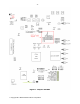
Note: The board comes equipped with DC-blocks applied to the I-channel signal input
connectors and DC blocks and terminators applied to the unused Q-channel input
connectors. These must be used at all times - that is, the channel being used must be
connected through dc-blocks if the ADC is configured for ac-coupled operation (as
shipped). The unused channel must also be DC blocked then terminated to ac ground.
This is graphically illustrated in Figure 3.
6. Turn on the SW2 rocker power switch. Verify that the red LED (labeled LD10, near the
J12 power jack) is lit.
7. Connect the supplied USB 2.0 cable from the PC USB port to the ADC12D1X00RFRB
USB jack.