
Datasheet
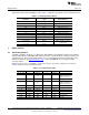
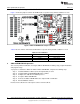
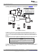
Table Of Contents
+5VA
-5VA
+5VD
+3.3V
+1.8V
+10V
-10V
PWR&VREF
USB
USB
RESET
DAC1220
TUSB3410
MSP430F449
+1
-1
DAC
IN
OUT
Analog
Daughtercard
Modular
Connectors
Power
Powerfrom
PWR&VREFBlock
Serial
Joystick
RESET
OPER
LCDDISPLAY
BSL
2.5V
Suppliedto
Daughtercard
PowerConnector
ADS1115EVM-PDK Kit Operation
www.ti.com
6.2.1 About the MMB3
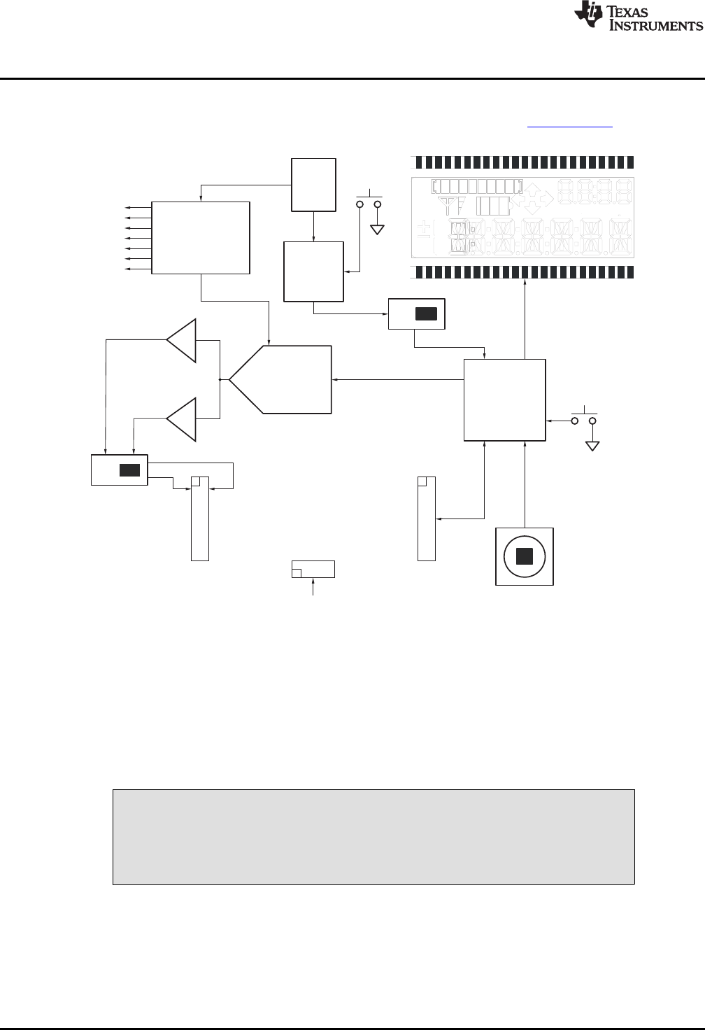
The MMB3 is a Modular EVM System motherboard. It is designed around the MSP430F449, a low-power
microcontroller from Texas Instruments. Figure 6 shows a block diagram of the MMB3.
Figure 6. MMB3 Block Diagram
The MMB3 was designed to be used as a stand-alone demonstration platform for low-speed data
converters. It features an onboard, 20-bit digital-to-analog converter (DAC) that can be used as a signal
source for an ADC under test, and has a joystick for control of functions on the board when it is not
controlled by a PC. These features are experimental and not supported in the ADS1115EVM-PDK at
this time.
The MMB3 derives power from the USB interface, and generates +5VD, 3.3V, and 1.8V, as well as +5VA
and –5VA and ±10V. The ±10V is supplied to the daughtercard power connector as +VA and –VA.
CAUTION
When using the ADS1115EVM connected to the MMB3, do not move switch S1
to the +VA position. This switch position will apply +10V to the devices on the
EVM and damage the EVM.
The MMB3 is not sold as a microcontroller development board, and it is not available separately. TI cannot
offer support for the MMB3 except as part of an EVM kit. For schematics or other information about the
MMB3, contact Texas Instruments.
10
ADS1015EVM, ADS1115EVM, ADS1015EVM-PDK, and ADS1115EVM-PDK SBAU157B–August 2009–Revised May 2011
Submit Documentation Feedback
Copyright © 2009–2011, Texas Instruments Incorporated