
Datasheet
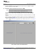
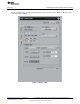
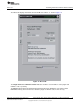

Table Of Contents

Evaluating Performance with the ADCPro Software
www.ti.com
The I2C Address groupbox contains controls related to the setting of the I
2
C address of Device 1. The
JMP2 Settings control is set up to mimic the layout of JMP2 on the EVM. When, for example, a jumper is
installed in the rightmost position, connecting the ADS1115 ADDR pin to GND, the GND radio button
should be selected here.
Whenever the JMP2 settings are changed, the I
2
C address of the device is changed, and the
corresponding address value is shown in the 7 bit and 8 bit indicators. The 7 bit indicator shows the
address considering only the seven bits that set the address of the device; the 8 bit indicator reflects how
a byte would actually be viewed if the eighth bit (the R/W bit) is set to zero.
The ACK light will reflect whether or not the address selected returns an I
2
C acknowledgement. If this light
is red, then no device was found at that address. This result may indicate that the jumper settings on the
EVM do not match the selection in the JMP2 Settings. A red light may also indicate that the two devices
on the board have been set to the same I
2
C address, and this state will be indicated by a message at the
top of the plug-in that says I2C Address Conflict. The two devices on the ADS1115EVM must be set for
different I
2
C addresses in order for the plug-in to operate. When a valid I
2
C address is selected, the ACK
light will turn green, indicating that a valid address has been found on the bus.
The Mux Setting control determines which set of inputs is used, displayed as AINP:AINN, where AINP is
the input connected to the positive input of the ADC, and AINN is the input connected to the negative input
of the ADC. Selections available are AIN0:AIN1, AIN0:AIN3, AIN1:AIN3, AIN2:AIN3, AIN0:GND,
AIN1:GND, AIN2:GND, or AIN3:GND.
The PGA Gain control sets the PGA gain. Selections available are 0.66666, 1, 2, 4, 8, or 16.
The Comparator groupbox contains controls related to the comparator functions of the ADS1115. The
Queue control selects whether to Disable Comparator, or to enable the comparator and have it Assert
after one conversion, Assert after two conversions, or Assert after four conversions. The comparator
output status is reflected by the D1 LED on the EVM.
The Mode switch allows selection of the comparator mode, either Traditional or Window. The Action
switch selects between Non-latching or Latching operation, and the Polarity switch determines if the
ALERT output of the device is Active Low or Active High. More details on these settings can be found in
the product data sheet.
The LO_THRESH and HI_THRESH controls set the numbers that are placed in corresponding low and
high threshold registers of the ADS1115. These numbers are displayed and entered in decimal format.
7.1.3 Device 2 Tab
This tab is identical to the Device 1 tab, but controls the settings for Device 2, which is U2 on the
ADS1115EVM.
18
ADS1015EVM, ADS1115EVM, ADS1015EVM-PDK, and ADS1115EVM-PDK SBAU157B–August 2009–Revised May 2011
Submit Documentation Feedback
Copyright © 2009–2011, Texas Instruments Incorporated