
Datasheet
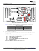
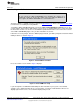
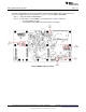
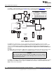
Table Of Contents

www.ti.com
Contents
1 EVM Overview ............................................................................................................... 3
2 Analog Interface ............................................................................................................. 3
3 Digital Interface .............................................................................................................. 4
4 Power Supplies .............................................................................................................. 5
5 EVM Operation .............................................................................................................. 5
6 ADS1115EVM-PDK Kit Operation ........................................................................................ 6
7 Evaluating Performance with the ADCPro Software .................................................................. 15
8 Schematics and Layout ................................................................................................... 21
List of Figures
1 ADS1115EVM Default Jumper Locations................................................................................ 6
2 Virtual COM Port Installer.................................................................................................. 7
3 Virtual COM Port Setup .................................................................................................... 7
4 MMB3 Switch Locations.................................................................................................... 8
5 Connecting ADS1115EVM to MMB3 ..................................................................................... 9
6 MMB3 Block Diagram..................................................................................................... 10
7 ADCPro Software Start-up Display Window ........................................................................... 11
8 ADS1115EVM-PDK Plug-In Display Window.......................................................................... 12
9 Connection Timeout....................................................................................................... 13
10 Firmware Download Message Box...................................................................................... 13
11 Firmware Download Progress Indicator ................................................................................ 14
12 Firmware Download Complete Message Box ......................................................................... 15
13 Device 1 Tab............................................................................................................... 17
14 About Tab .................................................................................................................. 19
15 Progress Bar While Collecting Data .................................................................................... 20
List of Tables
1 J1: Analog Interface Pinout................................................................................................ 4
2 J3: Serial Interface Pins.................................................................................................... 4
3 J2 Configuration: Power-Supply Input.................................................................................... 5
4 JMP1 Configuration: Power Options ..................................................................................... 5
5 List of Switches.............................................................................................................. 6
6 ADS1015EVM/ADS1115EVM Bill of Materials ....................................................................... 22
2
ADS1015EVM, ADS1115EVM, ADS1015EVM-PDK, and ADS1115EVM-PDK SBAU157B–August 2009–Revised May 2011
Submit Documentation Feedback
Copyright © 2009–2011, Texas Instruments Incorporated