
Datasheet
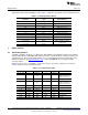
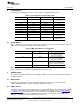
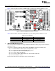
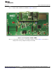
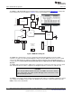
Table Of Contents

ADS1115EVM-PDK Kit Operation
www.ti.com
5.3 Default Jumper Settings and Switch Positions
Figure 1 shows the jumpers found on the EVM and the respective factory default conditions for each.
Figure 1. ADS1115EVM Default Jumper Locations
Table 5 lists the switches found on the EVM and the respective factory default conditions for each.
Table 5. List of Switches
Switch Position Switch Description
S1 Right (default) VDD = +3.3VD
Center VDD = +5VD
Left VDD = +VA
6 ADS1115EVM-PDK Kit Operation
This section provides information on using the ADS1115EVM-PDK, including setup, program installation,
and program usage.
To prepare to evaluate the ADS1115 with the ADS1115EVM-PDK, complete the following steps:
Step 1. Install the ADCPro software (if not already installed) on a PC.
Step 2. Install the ADS1115EVM-PDK EVM plug-in software.
Step 3. Complete the USB driver installation process.
Step 4. Set up the ADS1115EVM-PDK.
Step 5. Connect the ADS1115EVM-PDK to the computer with a USB cable.
Step 6. Run the ADCPro software.
Each task is described in the subsequent sections of this document.
6
ADS1015EVM, ADS1115EVM, ADS1015EVM-PDK, and ADS1115EVM-PDK SBAU157B–August 2009–Revised May 2011
Submit Documentation Feedback
Copyright © 2009–2011, Texas Instruments Incorporated