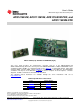
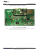
User's Guide SBAU157B – August 2009 – Revised May 2011 ADS1015EVM, ADS1115EVM, ADS1015EVM-PDK, and ADS1115EVM-PDK ADS1115EVM (Left) and ADS1115EVM-PDK (Right) This user's guide describes the characteristics, operation, and use of the ADS1015EVM and ADS1115EVM, both by themselves and as part of the ADS1015EVM-PDK or ADS1115EVM-PDK.
www.ti.com 1 2 3 4 5 6 7 8 Contents EVM Overview ............................................................................................................... 3 Analog Interface ............................................................................................................. 3 Digital Interface .............................................................................................................. 4 Power Supplies ........................................................................
EVM Overview www.ti.com 1 EVM Overview 1.1 Features ADS1015EVM/ADS1115EVM Features: • Contains all support circuitry needed for the ADS1015/ADS1115 • Two ADS1015/ADS1115 devices onboard to demonstrate I2C™ bus functionality • +3.
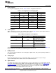
Digital Interface www.ti.com All of the pins on J1 are connected directly to the ADS1115 device input pins, with no protection. Use appropriate caution when handling these pins. Table 1 summarizes the pinouts for the analog interface J1. Table 1. J1: Analog Interface Pinout Pin Number Signal Description, ADS1015/ADS1115 J1.2 A0(+) AIN0, Device 1 (U1) J1.4 A1(+) AIN1, Device 1 (U1) J1.6 A2(+) AIN2, Device 1 (U1) J1.8 A3(+) AIN3, Device 1 (U1) J1.10 A0(+) AIN0, Device 2 (U2) J1.
Power Supplies www.ti.com 4 Power Supplies J2 is the power-supply input connector. Table 3 lists the configuration details for J2. Table 3. J2 Configuration: Power-Supply Input 4.1 Pin No. Pin Name Function Required J2.1 +VA External analog supply If 3.3 or 5V supplies not used J2.2 –VA Unused No J2.3 +5VA Unused No J2.4 –5VA Unused No J2.5 DGND Digital ground input Yes J2.6 AGND Analog ground input Yes J2.7 +1.8VD Unused No J2.8 VD1 Unused No J2.9 +3.3VD 3.
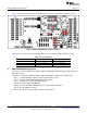
ADS1115EVM-PDK Kit Operation 5.3 www.ti.com Default Jumper Settings and Switch Positions Figure 1 shows the jumpers found on the EVM and the respective factory default conditions for each. Figure 1. ADS1115EVM Default Jumper Locations Table 5 lists the switches found on the EVM and the respective factory default conditions for each. Table 5. List of Switches 6 Switch Position Switch Description S1 Right (default) VDD = +3.
ADS1115EVM-PDK Kit Operation www.ti.com 6.1 Installing the ADCPro Software CAUTION Do not connect the ADS1115EVM-PDK before installing the software on a suitable PC. Failure to observe this caution may cause Microsoft Windows to not recognize the ADS1115EVM-PDK as a connected device. The latest software is available from the TI website at http://www.ti.com. Refer to the ADCPro User Guide for instructions on installing and using ADCPro.
ADS1115EVM-PDK Kit Operation 6.2 www.ti.com Setting Up the ADS1115EVM-PDK The ADS1115EVM-PDK contains both the ADS1115EVM and the MMB3 motherboard; however, the devices are shipped unconnected. Follow these steps to set up the ADS1115EVM-PDK. Step 1. Unpack the ADS1115EVM-PDK kit. Step 2. Set the switches on the MMB3 as described below, as Figure 4 illustrates. • Set switch SW4 to the right. • Set the DAC switch (SW5) to the OUT position (to the right). Figure 4.
ADS1115EVM-PDK Kit Operation www.ti.com space Step 3. Plug the ADS1115EVM into the MMB3 as Figure 5 illustrates. Figure 5. Connecting ADS1115EVM to MMB3 Step 4. Set the jumpers and switches on the ADS1115EVM as shown in Figure 1 (note that these settings are the factory-configured settings for the EVM).
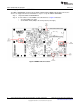
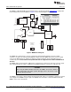
ADS1115EVM-PDK Kit Operation 6.2.1 www.ti.com About the MMB3 The MMB3 is a Modular EVM System motherboard. It is designed around the MSP430F449, a low-power microcontroller from Texas Instruments. Figure 6 shows a block diagram of the MMB3. USB USB RESET +5VA -5VA +5VD PWR & VREF +3.3V +1.8V +10V TUSB3410 -10V Supplied to Daughtercard Power Connector LCD DISPLAY 2.
ADS1115EVM-PDK Kit Operation www.ti.com 6.3 EVM Power Supply The ADS1115EVM-PDK is powered completely from the USB connection on the MMB3. The MMB3 provides 3.3V and 5V to the ADS1115EVM. 6.4 Running the Software and Download of Firmware to MMB3 NOTE: The software is continually under development. These instructions and screen images are current at the time of this writing, but may not exactly match future releases. The program for evaluating the ADS1115EVM-PDK is called ADCPro.
ADS1115EVM-PDK Kit Operation space Step 2. www.ti.com Select ADS1115EVM from the EVM drop-down menu. The ADS1115EVM-PDK plug-in appears in the left pane, as Figure 8 shows. Figure 8. ADS1115EVM-PDK Plug-In Display Window Step 3. 12 The ADS1115EVM-PDK plug-in window has a status area at the top of the screen. When the plug-in is first loaded, the plug-in searches for the board. You will see a series of messages in the status area indicating this action.
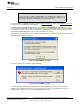
ADS1115EVM-PDK Kit Operation www.ti.com space Step 4. If the plug-in cannot connect to the EVM, you will see a window as shown in Figure 9. This message may indicate that the firmware is not loaded on the MMB3. You may select Retry Auto Connect; if that action fails, select Retry Manual Connect and specify the COM port to be used. Figure 9. Connection Timeout Step 5. The plug-in will detect whether or not the board has the correct firmware loaded.
ADS1115EVM-PDK Kit Operation www.ti.com Switch the BSL switch (SW4) on the MMB3 to the BSL position (to the left) as instructed, then press OK. The plug-in will download the firmware to the MMB3. This operation may take a couple of minutes, so the progress is updated in the message at the top of the ADS1115 plug-in window (as Figure 11 shows). The firmware is saved in flash memory on the MMB3, so this operation should only need to be performed once. Figure 11.
Evaluating Performance with the ADCPro Software www.ti.com When the firmware download completes, the message box shown in Figure 12 appears. Follow the on-screen instructions and the plug-in should now connect to the EVM. Figure 12. Firmware Download Complete Message Box 7 Evaluating Performance with the ADCPro Software The evaluation software is based on ADCPro, a program that operates using a variety of plug-ins. To use ADCPro, load an EVM plug-in and a test plug-in.
Evaluating Performance with the ADCPro Software 7.1.1 www.ti.com Data Rate and Sampling Information The Data Rate control on the main plug-in window sets the data rate for both ADS1115 converters on the EVM. It is a requirement of the ADCPro software that both devices operate at the same data rate. The ADS1115EVM-PDK always operates the device in continuous conversion mode; one-shot power-down mode is not supported.
Evaluating Performance with the ADCPro Software www.ti.com 7.1.2 Device 1 Tab This tab, shown in Figure 13, is the primary tab that controls all features of the ADS1115. Device 1 refers to U1 on the ADS1115EVM. Figure 13.
Evaluating Performance with the ADCPro Software www.ti.com The I2C Address groupbox contains controls related to the setting of the I2C address of Device 1. The JMP2 Settings control is set up to mimic the layout of JMP2 on the EVM. When, for example, a jumper is installed in the rightmost position, connecting the ADS1115 ADDR pin to GND, the GND radio button should be selected here.
Evaluating Performance with the ADCPro Software www.ti.com 7.1.4 About Tab The About tab displays information about the EVM and software, as shown in Figure 14. Figure 14. About Tab The Plugin Version and Firmware Version indicators show the version numbers of the plug-in and firmware code, respectively. The Notes indicator will show manufacturing information about the EVM that is stored in the EVM EEPROM, and may show relevant notes about the plug-in or firmware code, if there are any.
Evaluating Performance with the ADCPro Software 7.1.5 www.ti.com Collecting Data Once you have configured the ADS1115 for your test scenario, press the ADCPro Acquire button to start the collection of the number of datapoints specified in the Test plug-in Block Size control. The ADS1115EVM-PDK plug-in disables all the front panel controls while acquiring, and displays a progress bar as shown in Figure 15. Figure 15.
Schematics and Layout www.ti.com 7.2 Troubleshooting • • • 8 If the ADS1115EVM plug-in cannot find the ADS1115EVM-PDK, press the USB RESET button on the MMB3 (refer to Figure 4) and try again. If the MMB3 board is unable to be detected, there may be conflicting settings for the COM port assignments on your PC that requires manual configuration. 1. Open the Device Manager application under Windows. You should observe an item entitled USB-Serial Port under the Ports (COM&LPT) menu. 2.
Schematics and Layout 8.1 www.ti.com Bill of Materials NOTE: All components should be compliant with the European Union Restriction on Use of Hazardous Substances (RoHS) Directive. Some part numbers may be either leaded or RoHS. Verify that purchased components are RoHS-compliant. (For more information about TI's position on RoHS compliance, see the TI web site.) Table 6. ADS1015EVM/ADS1115EVM Bill of Materials 22 Item No.
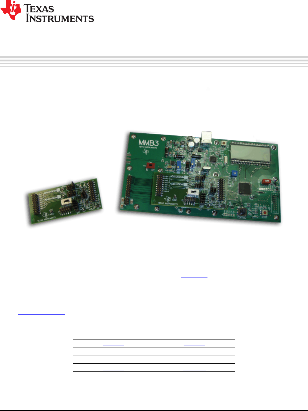
1 2 3 4 5 6 REVISION HISTORY REV ENGINEERING CHANGE NUMBER APPROVED D D VDD VDD R3 470 R4 470 D1 LED VDD R1 1K VDD1 VDD1 B AIN0 AIN1 AIN2 AIN3 GND 2 4 6 8 10 8 1 2 9 10 VDD ADDR ALERT/RDY SDA SCL 1k U5B 5 3 SN74LVC2G125DCU JPR-2X4 2 4 6 8 10 12 14 16 18 20 GPIO0 DGND GPIO1 GPIO2 DGND GPIO3 GPIO4 SCL DGND SDA CNTL CLKX CLKR FSX FSR DX DR INT TOUT GPIO5 1 3 5 7 9 11 13 15 17 19 DAUGHTER-SERIAL VDD +3.3VD C3 S1 ESW_EG2305A JMP1 VDD1 1 3 5 7 VDD2 VDD 0.1uF R7 200K 0.
Evaluation Board/Kit Important Notice Texas Instruments (TI) provides the enclosed product(s) under the following conditions: This evaluation board/kit is intended for use for ENGINEERING DEVELOPMENT, DEMONSTRATION, OR EVALUATION PURPOSES ONLY and is not considered by TI to be a finished end-product fit for general consumer use. Persons handling the product(s) must have electronics training and observe good engineering practice standards.
IMPORTANT NOTICE Texas Instruments Incorporated and its subsidiaries (TI) reserve the right to make corrections, modifications, enhancements, improvements, and other changes to its products and services at any time and to discontinue any product or service without notice. Customers should obtain the latest relevant information before placing orders and should verify that such information is current and complete.