
Datasheet

www.ti.com
Analysis Mode
3 Analysis Mode
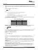
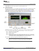
In Analysis mode, the ADS1x31REF analyzes code output from the installed ADS device and displays it in
different ways. Table 3 summarizes the numerous display modes available, together with example
displays.
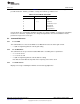
NOTE: The values shown in Table 3 are consistent for a 24-bit device, such as the ADS1231.
However, the ADS1131 is an 18-bit device, so the actual number of codes will be fewer than
the examples shown here.
Table 3. Modes and Example Displays
Hex Code Dec Code Voltage ENOB
Raw 1992E9H +1676001 +499.488M n/a
RMS n/a +5.789 +17.495N +23.18BIT
Peak-to-Peak n/a +31.256 +90.293N +21.92BIT
Averaged n/a +1676001 +499.488M n/a
The ADS1x31REF operates in Analysis mode when the mode switch is set to the ANALYSIS position.
The default Analysis mode is RAW HEX.
To change measurement types, hold down DISP and press MODE. This function cycles through the four
available measurement types. When DISP is released, the newly selected measurement is made. To
change units, press UNIT. This option cycles through the available units for the active measurement type.
This procedure can also be done while DISP is depressed; in that case, the new unit is shown by name
on the display. The measurement modes are described in detail in Section 3.2.
The ADS1131 or ADS1231 itself can be configured directly from this mode, as described in Section 3.1.
3.1 Switch Functions
NEW BLOCK: Pressing this switch resets the collection process for the RMS, peak-to-peak, and
averaged measurements.
UNIT: Cycles between available units. Not all units are available in all modes.
DISP: When this switch is pressed, the display shows the current measurement mode and unit. While
DISP is still pressed, pressing NEW BLOCK / MODE cycles through the available measurement modes.
CHIP: Holding this switch down allows the settings of the installed ADS device to be changed, using the
PARM (NEW BLOCK) and VAL (UNIT) buttons.
Pressing PARM while CHIP is pressed down cycles through the available parameters of gain and data
rate.
The gain setting is displayed as GAIN= followed by the gain setting. The gain setting is for display only,
because the gain is fixed at 64 for the ADS1131 and 128 for the ADS1231.
Data rate is shown on the display as SPD=FAST or SPD=SLOW. See ADC speed in the Parameters section
for further information.
If any of these parameters are changed during a multisample measurement, the measurement is
restarted.
11
SBAU175A–July 2010–Revised August 2011 ADS1131REF and ADS1231REF
Submit Documentation Feedback
Copyright © 2010–2011, Texas Instruments Incorporated