
Datasheet

v =
B 1-
x
v
REF
A
·
s =
N
(x )-
i
x
2
N
i =1
1
N
å
E =
N log s :-
2 N
0s
N
¹
24 : s 0
N
=
Analysis Mode
www.ti.com
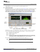
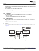
3.2 Measurement Modes
Raw: In this measurement, codes are read from the installed ADS device and displayed. No processing or
analysis is done on the sample stream. Data can be displayed as hexadecimal codes, decimal codes, or
volts.
Voltage is calculated according to Equation 3:
Where:
• A is the converter gain (64 for the ADS1131 and 128 for the ADS1231)
• v
REF
is the voltage at the converter reference input
• x is the ADC decimal code
• B is the number of converter bits, 2
18
for the ADS1131 and 2
24
for the ADS1231 (3)
v
REF
is adjustable from Configuration mode. By default, it is 5V.
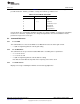
The voltage display is autoranging. All ranges are shown with six significant figures having three decimal
places. The ranges are given in Table 4.
Table 4. Voltage Display Ranges
VOLTAGE RANGE DISPLAY SUFFIX
Nanovolts < 1μV n
Microvolts < 1mV u
Millivolts < 1V m
Volts ≥ 1V V
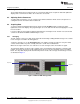
RMS noise: In this mode, a number of codes are read from the installed ADS device, and an RMS noise
calculation is performed on them using the standard-deviation formula (given in Equation 4):
(4)
The result can be displayed as decimal codes, volts, or an effective number of bits (ENOB). For decimal
codes, s
N
is displayed directly. (Hexadecimal is not available because s
N
may be fractional.) For volts, s
N
is converted to a voltage as in raw mode.
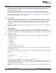
ENOB: E is calculated using Equation 5:
(5)
Where N is the maximum number of available bits (18 for the ADS1131 and 24 for the ADS1231).
The zero case is needed when a string of equal codes is read. This can happen when the converter is
clipping.
This measurement requires a number of codes to be read before a calculation can be made. Therefore,
during the first run, the display shows the word GOT followed by the number of samples collected. This
event happens when the mode is first entered, when the converter configuration changes, or when NEW
BLOCK is pressed.
The number of codes used in the calculation is selected in Configuration mode; 50 codes are used in
laboratory characterization, so this value is the default.
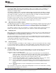
Peak-to-peak noise: In this mode, a number of codes are collected, and the absolute value of the
difference between the minimum and maximum is calculated. The result can be displayed in decimal or
hexadecimal codes, volts, or noise-free bits (ENOB). Volts are calculated as in raw mode; ENOB is
calculated in the same way as in RMS mode.
12
ADS1131REF and ADS1231REF SBAU175A–July 2010–Revised August 2011
Submit Documentation Feedback
Copyright © 2010–2011, Texas Instruments Incorporated