
Datasheet

www.ti.com
Analysis Mode
The number of codes used in the calculation is selectable in Configuration mode.
Averaged: In this mode, a number of codes are collected, and the average is calculated. The result can
be displayed in decimal codes or volts. (Hexadecimal is not available because the result may be
fractional.) Volts are calculated as in raw mode.
The number of codes used in the calculation is selectable in Configuration mode.
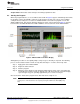
3.3 Progress Graph
The row of apostrophes at the top of the display are used to indicate measurement progress. In Raw
mode, the apostrophe moves across the display when data is being received from the converter.
In block collection modes, the apostrophes form a bar graph. As the collection of a block proceeds, the
bar graph increases. When the bar graph reaches all the way to the right, the new result is generated and
collection restarts.
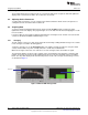
3.4 Configuration
To enter Configuration mode, press the PARM buttons simultaneously. The four buttons then assume the
functions shown in the CONFIG box. To exit Configuration mode, press the PARM buttons simultaneously
again. This operation does not cause parameters to be adjusted; only button releases are detected in
Configuration mode.
Configuration mode contains a number of adjustable parameters. To scroll through the available
parameters, use the PARM buttons. To change the parameter values, use the VALUE buttons.
Some items in configuration mode are not parameters, but commands or gateways to a submenu. These
items are labelled as words with a question mark. To enter these items or to execute the command, press
SEL or ENT.
Although a few of the parameters in the Analysis and Scale configuration menus are the same, the
settings are kept separate between the modes.
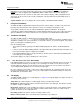
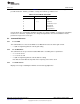
Table 5 summarizes the available parameters.
Table 5. Parameters in Analysis Mode
Parameter Display Value Range Description
Averages AVG= 2–128 Number of points for average,
peak-to-peak, and RMS modes
Voltage Reference VREF= 0.5–5.0 Voltage used in various
calculations
Power-down mode PDWN? — Power-down mode; see text
Save parameters SAVE? — Save parameters; see text
Version number V1.0.0 — Firmware version number display
3.4.1 Parameters
Averages: Number of points to use in Averaged, RMS noise, and Peak-Peak calculations. The choices
available are 2, 4, 8, 10, 16, 32, 50, 64, and 128. The default setting is 50.
Voltage reference: To convert voltages to codes, the ADS1x31REF requires the voltage reference level.
Since this level cannot be measured, it must be selected manually. This parameter allows the reference
level to be set.
Each digit of the voltage reference is selected and adjusted separately. Use the PARM buttons to select a
digit, and the VALUE buttons to adjust it. The selected digit flashes.
This parameter does not affect the actual voltage reference used. If it is incorrect, voltage calculations will
be wrong. The voltage reference is typically the +5V rail; the default value for this parameter is 5.0V.
13
SBAU175A–July 2010–Revised August 2011 ADS1131REF and ADS1231REF
Submit Documentation Feedback
Copyright © 2010–2011, Texas Instruments Incorporated