
Datasheet

www.ti.com
Contents
1 Getting Started .............................................................................................................. 3
2 Weigh Scale Mode .......................................................................................................... 7
3 Analysis Mode ............................................................................................................. 11
4 Using the PC Software ................................................................................................... 14
5 Serial Console ............................................................................................................. 18
6 Hardware ................................................................................................................... 20
Appendix A Schematic and Layout ........................................................................................... 23
List of Figures
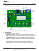
1 ADS1x31REF Controls and Connectors ................................................................................. 3
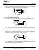
2 4-Wire Load Cell to Terminal Block ...................................................................................... 4
3 6-Wire Load Cell to Terminal Block ...................................................................................... 5
4 4-Wire Load Cell to Header................................................................................................ 5
5 6-Wire Load Cell to Header................................................................................................ 5
6 ADS1231REF PC Software Display .................................................................................... 15
7 ADS1x31REF Average Data............................................................................................. 16
8 ADS1x31REF Hardware Block Diagram ............................................................................... 20
9 ADS1x31REF PCB—Top Side .......................................................................................... 25
10 ADS1x31REF PCB—Layer 1 ............................................................................................ 25
11 ADS1x31REF PCB—Layer 2 ............................................................................................ 26
12 ADS1x31REF PCB—Bottom Side ...................................................................................... 26
13 ADS1x31REF Schematic—ADC ........................................................................................ 27
14 ADS1x31REF Schematic—MCU ........................................................................................ 27
15 ADS1x31REF Schematic—USB......................................................................................... 28
List of Tables
1 Unit Conversion Factors and Display Formats.......................................................................... 8
2 Parameters in Configuration Mode ....................................................................................... 9
3 Modes and Example Displays ........................................................................................... 11
4 Voltage Display Ranges .................................................................................................. 12
5 Parameters in Analysis Mode............................................................................................ 13
6 Console Mode Commands............................................................................................... 19
7 Load Cell Header Pinout ................................................................................................. 21
8 Terminal Block Pinout..................................................................................................... 22
9 ADS1x31REF Bill of Materials .......................................................................................... 23
2
ADS1131REF and ADS1231REF SBAU175A–July 2010–Revised August 2011
Submit Documentation Feedback
Copyright © 2010–2011, Texas Instruments Incorporated