
Datasheet

EXC-
SNS-
SNS+
SIG+
SIG-
EXC+
OUT+
EXC-
OUT-
EXC+
Getting Started
www.ti.com
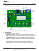
1.2 Controls
The main controls for the ADS1x31REF are the four buttons and the mode selection slide-switch (see
Figure 1).
The slide-switch selects between weigh-scale (Scale) and Analysis modes. The ADS1x31REF switches
modes only when it is displaying data. If the switch is changed in a configuration mode, nothing happens
until the configuration mode is exited. At that time the ADS1x31REF reads the switch and enters the
selected mode.
The four buttons have different functions, depending on the operating mode. In Scale mode, the switches
have the functions in the box labeled SCALE. In Analysis mode, the switches have the functions shown in
the box labeled ANALYSIS. In configuration mode, the switches have the functions shown in the box
labeled CONFIG.
The buttons also have different names in different modes. In this document, they are identifed by the
respective names they have in the mode under discussion.
1.2.1 Auxiliary Controls
The Reset switch resets the board, except for the USB interface.
The USB Reset switch resets the USB interface. If USB communication fails, pressing USB Reset may
solve the problem.
The Programming Mode switch is used to update the firmware. For normal operation, it should be set to
JTAG.
1.3 Power
To apply power to the ADS1x31REF, connect a 9V battery or plug in a 6V–9V ac wall adapter.
AC adapters must be tip positive/sleeve negative. When an ac adapter is plugged in, the board always
takes power from it, and not from the battery.
The ADS1x31REF is protected against polarity reversal. If a power source is connected in reverse by
mistake, the display remains blank. To prevent damage to the board, do not leave a reversed power
source connected for longer than a few seconds.
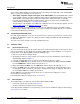
1.4 Connecting a Load Cell
The ADS1x31REF is specifically designed for connection to load cells. Two connectors are provided for
this application. The terminal block is used for load cells having stripped wire connections; the load cell
header is for load cells having a header connector. The terminal block provides connections to the
reference input (or power supply) and the header has switched excitation.
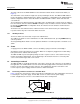
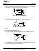
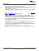
1.4.1 Connecting a 4-Wire Load Cell to the Terminal Block
Figure 2 shows the connection of a 4-wire load cell to the terminal block. In this configuration, the load cell
is excited by the +5V power supply, and the ADC reference is taken from the power supply.
For this configuration, the reference select switch must be in the +5VA position.
Figure 2. 4-Wire Load Cell to Terminal Block
4
ADS1131REF and ADS1231REF SBAU175A–July 2010–Revised August 2011
Submit Documentation Feedback
Copyright © 2010–2011, Texas Instruments Incorporated