
Datasheet

EXC-
SNS-
SNS+
SIG+
SIG-
EXC+
OUT+
EXC-
SENSE-
OUT-
SENSE+
EXC+
OUT+
EXC-
OUT-
EXC+
1
2
3
4
5
6
OUT-
EXC+
OUT+
EXC-
SENSE+
SENSE-
1
2
3
4
5
6
www.ti.com
Getting Started
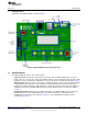
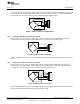
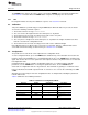
1.4.2 Connecting a 6-Wire Load Cell to the Terminal Block
Figure 3 shows the connection of a 6-wire load cell to the terminal block. In this configuration, the load cell
is excited by the +5V power supply, and the ADC’s reference is taken from the sense wire returning from
the load cell. The sense wire connects to the excitation wire at the bridge sensor.
Figure 3. 6-Wire Load Cell to Terminal Block
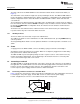
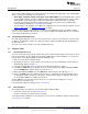
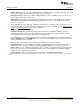
1.4.3 Connecting a 4-Wire Load Cell to the Header
Figure 4 shows the connection of a 4-wire load cell to the header. In this configuration, the load cell is
excited by the +5V power supply, and the ADC reference is taken from the power supply.
Figure 4. 4-Wire Load Cell to Header
For this configuration, the reference select switch must be in the +5VA position; the EXT position does not
work.
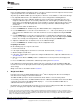
1.4.4 Connecting a 6-Wire Load Cell to the Header
Figure 5 shows the connection of a 6-wire load cell to the header. In this configuration, the load cell is
excited by the +5V power supply, and the ADC reference is taken from the sense wire returning from the
load cell. The sense wire connects to the excitation wire at the bridge sensor.
Figure 5. 6-Wire Load Cell to Header
For this configuration, the reference select switch should be in the EXT position for best performance. The
+5V position also works, but the device may not perform as well.
5
SBAU175A–July 2010–Revised August 2011 ADS1131REF and ADS1231REF
Submit Documentation Feedback
Copyright © 2010–2011, Texas Instruments Incorporated