
Datasheet

DOUT
DRDY/FSYNC (Frame-Sync Format)
DIN
DOUT
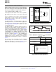
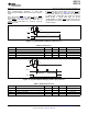
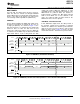
FRAME-SYNC SERIAL INTERFACE
DIN
SCLK
ADS1174
ADS1178
SBAS373B – OCTOBER 2007 – REVISED SEPTEMBER 2008 ........................................................................................................................................
www.ti.com
will be corrupted. The number of SCLKs within a
frame period (FSYNC clock) can be any power of two
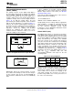
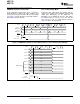
In Discrete Data Output mode, the conversion data
ratio of clock cycles (1, 1/2, 1/4, etc.), as long as the
are output on the individual DOUT pins (DOUT1,
number of cycles is sufficient to shift the data output
DOUT2, etc.), whereas in TDM mode, data are output
from all channels within one data frame.
only on DOUT1. The MSB data are valid on
DOUT[4:1]/[8:1] when DRDY goes low. The
subsequent bits are shifted out with each falling edge
of SCLK. If daisy-chaining (TDM mode), the data
In Frame-Sync format, this pin is used as the FSYNC
shifted in using DIN appear on DOUT1 after all
input. The frame-sync input (FSYNC) sets the frame
channel data have been shifted out.
period which must be same as the data rate. The
required number of f
CLK
cycles to each FSYNC period
depends on the mode selection and the CLKDIN
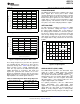
input. Table 4 indicates the number of CLK cycles to
This input is used when multiple ADS1174/78s are to
each frame (f
CLK
/f
DATA
). If the FSYNC period is not
be daisy-chained together. The DOUT1 pin of the first
the proper value, data readback is corrupted.
device connects to the DIN pin of the next, etc. It can
be used with either the SPI or Frame-Sync formats.
Data are shifted in on the falling edge of SCLK. When
using only one ADS1174/78, tie DIN low. See the
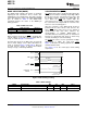
In Discrete Data Output mode, the conversion data
Daisy-Chaining section for more information.
are shifted out on the individual DOUT pins (DOUT1,
DOUT2, etc.), whereas in TDM mode, data are output
only on DOUT1. The MSB data become valid on
DOUT[4:1]/[8:1] on the SCLK rising edge prior to
Frame-Sync format is similar to the interface often
FSYNC going high. The subsequent bits are shifted
used on audio ADCs. It operates in slave
out with each falling edge of SCLK. If daisy-chaining
fashion — the user must supply framing signal FSYNC
(TDM mode), the data shifted in using DIN appear on
(similar to the left/right clock on stereo audio ADCs)
DOUT1 after all channel data have been shifted out
and the serial clock SCLK (similar to the bit clock on
(that is, 4 channels × 16 bits per channel = 64 bits for
audio ADCs). The data is output MSB first or
the ADS1174, and 8 channels × 16 bits per channel =
left-justified. When using Frame-Sync format, the
128 bits for the ADS1178).
FSYNC and SCLK inputs must be continuously
running with the required relationships shown in the
Frame-Sync Timing Requirements .
This input is used when multiple ADS1174/78s are to
be daisy-chained together. It can be used with either
SPI or Frame-Sync formats. Data are shifted in on
The serial clock (SCLK) features a Schmitt-triggered
the falling edge of SCLK. When using only one
input and shifts out data on DOUT on the falling
ADS1174/78, tie DIN low. See the Daisy-Chaining
edge. It also shifts in data on the falling edge on DIN
section for more information.
when this pin is being used for daisy-chaining. Even
though SCLK has hysteresis, it is recommended to
keep SCLK as clean as possible to prevent glitches
from accidentally shifting the data. When using
Frame-Sync format, SCLK must run continuously; if
SCLK is disabled or interrupted, the data readback
18 Submit Documentation Feedback Copyright © 2007 – 2008, Texas Instruments Incorporated
Product Folder Link(s): ADS1174 ADS1178