
Datasheet

www.ti.com
Clock Source
6 Clock Source
The ADS1246 has an internal clock or can be provided an external clock. The EVM uses the internal clock
mode only. Provision is made on the EVM circuit board, however, for an external clock source. A footprint
is provided at U8 for a crystal oscillator to be mounted on the board. An external clock may also be
provided by a processor on the TOUT pin (J7.17), or an external clock source connected to J9.1 (ground)
and J9.2 (signal).
J2 controls how the clock source is selected. With pins J2.1 and J2.2 shorted, GPIO5 from J7.19 can
control whether the A or B side of U7 is selected. If the A side is selected, the clock should come from an
external source provided as described above. If the B side is selected, the clock should come from the
crystal oscillator. If a selection is made and no clock is provided on that input, the ADS1246 detects that
no external clock is present and enables its internal oscillator.
6.1 Usage in PDK
If using the ADS1246EVM as part of the ADS1246EVM-PDK, remove any shorting blocks on jumper J6,
and make sure J2 has a jumper between pins 1 and 2 (the IO position). This configuration grounds the
CLK input to the ADS1246 and ensures that the internal oscillator starts up.
6.2 Usage as a Stand-Alone EVM
If using the EVM in your own system and not with the PDK hardware and software, observe the following
recommendations:
• J6 should be removed if the external clock source is used and the TOUT pin is still driven by a
processor in order to avoid conflicts.
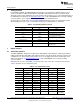
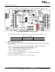
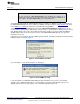
• Jumper J2 can be used to always select the U8 oscillator (DVDD position) or allow the
onboard/external clock selection to be controlled by GPIO5 (J7.19) as shown in Figure 2.
Figure 2. Jumper J2
7 EVM Operation
This section provides information on the analog input, digital control, and general operating conditions of
the ADS1246EVM.
7.1 Analog Input
The analog input source can be applied directly to J8 (top or bottom side) or through signal-conditioning
modules available for the the modular EVM system. Terminal block J4 is connected in parallel with the
analog signal connections to J8. The input has a 47Ω/47pF RC filter in series with it, and a differential
0.1μF capacitor is across the input pair for use with differential signals.
7.2 Digital Control
The digital control signals can be applied directly to J7 (top or bottom side). The modular ADS1246EVM
can also be connected directly to a DSP or microcontroller interface board, such as the 5-6K Interface or
HPA-MCU Interface boards available from Texas Instruments, or the MMB3 if purchased as part of the
ADS1246EVM-PDK. For a list of compatible interface and/or accessory boards for the EVM or the
ADS1246, see the relevant product folder on the TI web site.
7
SBAU149B–June 2009–Revised May 2011 ADS1146EVM, ADS1246EVM, ADS1146EVM-PDK, ADS1246EVM-PDK
Submit Documentation Feedback
Copyright © 2009–2011, Texas Instruments Incorporated