
Datasheet

Evaluating Performance with the ADCPro Software
www.ti.com
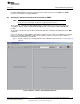
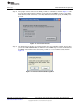
The System Monitor button allows you to access the internal system monitor channels of the ADS1246.
When pressed, this button disables the other analog input channel controls, and the system monitor
channel selections are enabled. You can select Offset, Gain, or Temperature as the channel to convert.
Note that some of these channels are scaled by a factor when read; refer to the ADS1246 data sheet to
determine these factors.
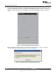
The PGA Gain control sets the PGA gain, and the Data Rate control sets the data rate for the device.
Note that the data rate can go quite low; therefore, if the block size is large, the time it takes to collect a
block of data can be quite long. It is advisable to first test collection at the higher data rates. Once a test is
known to work properly, drop down to the lower data rate and allow sufficient time to collect the data.
The BCS control sets the current level of the burnout current sources; it may be set Off, or to 0.5μA, 2μA,
or 10μA.
The Power Down control powers down the ADS1246. Note that no data can be collected if the Power
Down button is activated.
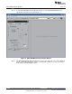
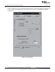
9.1.1.2 Supply Configuration
This section controls the selection of the power supply mode and reference voltage.
The Power Supply control selects between single supply (+5V) mode and bipolar supply (±2.5V) mode.
The EVM draws its supply voltages from the MMB3 motherboard, and has onboard circuitry to select
between the +5V and bipolar supplies.
The VREF value is set to 2.048V, with switch S1 set to BUFF. S1 should not be set to the AVDD position,
in order to prevent the reference from exceeding the maximum specified input.
20
ADS1146EVM, ADS1246EVM, ADS1146EVM-PDK, ADS1246EVM-PDK SBAU149B–June 2009–Revised May 2011
Submit Documentation Feedback
Copyright © 2009–2011, Texas Instruments Incorporated