
Datasheet

Voltage Reference
www.ti.com
4.1 Power Options
J10 is arranged as five rows, each of which can be shorted. Table 4 lists the power option details for J10.
For normal operation, J10.1-2, J10.3-4, and J10.5-6 must be connected (direct or through an ammeter),
and either (or both) of J10.7-8 and J10.9-10 must be connected; otherwise, the board will not function.
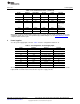
Table 4. J10 Configuration: Power Options
Row Name Function
1-2 ADC AVDD AVDD supply current measurement point for the
ADC. Must be connected for operation.
3-4 ADC AVSS AVSS supply current measurement point for the
ADC. Must be connected for operation.
5-6 ADC DVDD DVDD supply current measurement point for the
ADC. Must be connected for operation.
7-8 DGND Connects DGND to board ground.
9-10 AGND Connects AGND to board ground.
5 Voltage Reference
The ADS1246 device always uses an external reference. The EVM provides a 2.048V reference for the
device from U1, filtered and buffered through U2. This 2.048V may be used to drive the REFP input, or
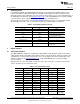
REFP can be connected to the external reference on J8 through switch S1. REFP should not be
connected to AVDD through switch S1 because this connection will violate the specification for the
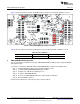
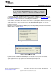
maximum reference input. Figure 1 shows switch S1 as it appears on the EVM. The low side of the
reference (REFN) is tied to AVSS. The different reference options under different supply conditions are
outlined in Table 5.
Figure 1. Reference Select Switch S1
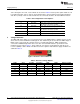
Table 5. Reference Voltage Options
AVDD AVSS J1 Setting S1 Position
(1)
REFP REFN Reference Voltage
5V 0V 1-2 BUFF 2.048V 0V 2.048V
5V 0V 2-3 BUFF 0V 0V Invalid Selection
5V 0V — Center REF+ (J8.20) 0V Up to AVDD – 1
2.5V –2.5V 1-2 BUFF –0.452V –2.5V 2.048V
2.5V –2.5V 2-3 BUFF 0V –2.5V 2.5V
2.5V –2.5V — Center REF+ (J8.20) –2.5V Up to AVDD – AVSS – 1
(1)
Switch S1 should not be set to AVDD.
6
ADS1146EVM, ADS1246EVM, ADS1146EVM-PDK, ADS1246EVM-PDK SBAU149B–June 2009–Revised May 2011
Submit Documentation Feedback
Copyright © 2009–2011, Texas Instruments Incorporated