
Datasheet

(MUXCAL=001)
SystemMonitors
Temperature
Diode
VREFP
VREFN
VREFP1/4
VREFN1/4
VREFP0/4
VREFN0/4
AVDD/4
AVSS/4
DVDD/4
DVSS/4
ADS1248Only
ADS1247/48Only
VBIAS
AIN0
AIN1
VBIAS
AIN2
VBIAS
AIN3
VBIAS
AIN4
VBIAS
AIN5
VBIAS
AIN6
VBIAS
AIN7
AVDD
IDAC1
IDAC2
AVDD
VBIAS
PGA
AIN
P
AVSS
AVDD
BurnoutCurrentSource
(0.5 A,2 A,10m m mA)
BurnoutCurrentSource
(0.5 A,2 A,10m m mA)
AIN
N
To
ADC
AVSS
AVSS
AVSS
AVSS
AVSS
AVSS
AVSS
AVSS
AVDD
AVDD
AVDD
AVDD
AVDD
AVDD
AVDD
AVDD
AVDD AVDD
Evaluating Performance with the ADCPro Software
www.ti.com
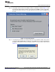
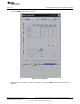
9.1.1 I/O Config Tab
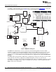
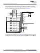
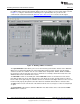
This tab is the primary tab that controls the function of the multiplexer in the ADS1247. Recall that the
ADS1247 multiplexer is configured as shown in Figure 15. By default, all channels are set as analog input;
the IDACs are not routed to any channel and the IDAC controls are disabled. These controls are enabled
when the correct IDAC settings are made on the Power & Ref tab (see Section 9.1.3).
Figure 15. ADS1247 Multiplexer
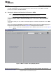
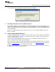
The radio buttons at the far right of the panel (see Figure 16) select which pair of inputs are connected to
the PGA. Note that you may select the same input for both the positive (AINP) and negative (AINN) input;
this configuration is often selected to perform a noise test on the ADC itself.
18
ADS1147EVM, ADS1247EVM, ADS1147EVM-PDK, ADS1247EVM-PDK SBAU148B– June 2009– Revised May 2011
Submit Documentation Feedback
Copyright © 2009–2011, Texas Instruments Incorporated