
Datasheet

www.ti.com
Contents
1 EVM Overview ............................................................................................................... 3
2 Analog Interface ............................................................................................................. 4
3 Digital Interface .............................................................................................................. 4
4 Power Supplies .............................................................................................................. 5
5 Voltage Reference .......................................................................................................... 6
6 Clock Source ................................................................................................................ 7
7 EVM Operation .............................................................................................................. 7
8 ADS1247EVM-PDK Kit Operation ........................................................................................ 8
9 Evaluating Performance with the ADCPro Software .................................................................. 17
10 Schematics and Layout ................................................................................................... 29
List of Figures
1 Reference Select Switch S1............................................................................................... 6
2 Jumper J2.................................................................................................................... 7
3 ADS1247EVM Default Jumper Locations................................................................................ 8
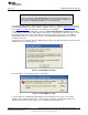
4 Virtual COM Port Installer.................................................................................................. 9
5 Virtual COM Port Setup .................................................................................................... 9
6 MMB3 Switch Locations .................................................................................................. 10
7 Connecting ADS1247EVM to MMB3 ................................................................................... 11
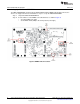
8 MMB3 Block Diagram..................................................................................................... 12
9 ADCPro Software Start-up Display Window ........................................................................... 13
10 ADS1247EVM-PDK Plug-In Display Window.......................................................................... 14
11 Connection Timeout....................................................................................................... 15
12 Firmware Download Message Box...................................................................................... 15
13 Firmware Download Progress Indicator ................................................................................ 16
14 Firmware Download Complete Message Box ......................................................................... 17
15 ADS1247 Multiplexer ..................................................................................................... 18
16 I/O Config Tab ............................................................................................................. 19
17 Enabling VBIAS on a Channel........................................................................................... 20
18 GPIO Tab .................................................................................................................. 21
19 GPIO Set to Output Mode................................................................................................ 22
20 GPIO Output Set to High ................................................................................................. 23
21 Power & Ref Tab .......................................................................................................... 24
22 Cal Tab ..................................................................................................................... 26
23 About Tab .................................................................................................................. 27
24 Progress Bar While Collecting Data .................................................................................... 28
List of Tables
1 J8/J4: Analog Interface Pinout ............................................................................................ 4
2 J7: Serial Interface Pins.................................................................................................... 4
3 J3 Configuration: Power-Supply Input.................................................................................... 5
4 J4 Configuration: Power Options ......................................................................................... 6
5 REF1 Reference Voltage Options ........................................................................................ 6
6 List of Switches.............................................................................................................. 8
7 ADS1147EVM/ADS1247EVM Bill of Materials ....................................................................... 29
2
ADS1147EVM, ADS1247EVM, ADS1147EVM-PDK, ADS1247EVM-PDK SBAU148B– June 2009– Revised May 2011
Submit Documentation Feedback
Copyright © 2009–2011, Texas Instruments Incorporated