
Datasheet

Evaluating Performance with the ADCPro Software
www.ti.com
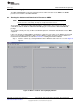
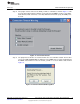
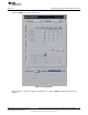
Each input channel can also have a VBIAS applied to it. Checking the VBIAS box on a channel applies
the VBIAS voltage, which is approximately half the value of the supply. You can test this option as shown
in Figure 17, using one channel tied to something close to ground (make sure you observe the
common-mode restrictions listed in the ADS1247 device data sheet) as a reference for this signal.
Figure 17. Enabling VBIAS on a Channel
The System Monitor button allows you to access the internal system monitor channels of the ADS1247.
When pressed, this button disables the other analog input channel controls, and the system monitor
channel selections are enabled. You can select Offset, Gain, Temperature, VREF0, AVDD or DVDD as
the channel to convert. Note that some of these channels are scaled by a factor when read; refer to the
ADS1247 data sheet to determine these factors.
The PGA Gain control sets the PGA gain, and the Data Rate control sets the data rate for the device.
Note that the data rate can go quite low; therefore, if the block size is large, the time it takes to collect a
block of data can be quite long. It is advisable to first test collection at the higher data rates. Once a test is
known to work properly, drop down to the lower data rate and allow sufficient time to collect the data.
The BCS control sets the current level of the burnout current sources; it may be set Off, or to 0.5μA, 2μA,
or 10μA.
The Power Down control powers down the ADS1247. Note that no data can be collected if the Power
Down button is activated.
20
ADS1147EVM, ADS1247EVM, ADS1147EVM-PDK, ADS1247EVM-PDK SBAU148B– June 2009– Revised May 2011
Submit Documentation Feedback
Copyright © 2009–2011, Texas Instruments Incorporated