
Datasheet

DS
Modulator1
Digital
Filter1
VREFP
V
IN1
VREFN
V
REF
S
TEST[1:0]
FORMAT[2:0]
CLK
SYNC
PWDN
(1)
[4:1]/[8:1]
CLKDIV
MODE[1:0]
DRDY/FSYNC
SCLK
DOUT[4:1]/[8:1]
(1)
DIN
SPI
and
Frame-Sync
Interface
Control
Logic
AINP1
AINN1
VCOM
S
DS
Modulator2
Digital
Filter2
V
IN2
S
AINP2
AINN2
DS
Modulator4/8
(1)
Digital
Filter4/8
(1)
V
IN4/8
S
AINP4/8
(1)
AINN4/8
(1)
DVDDAVDD
AGND DGND
IOVDD
R
R
Modulator
Output
Mod1
Mod2
Mod8
ADS1274
ADS1278
SBAS367F –JUNE 2007–REVISED FEBRUARY 2011
www.ti.com
OVERVIEW
High-Speed, High-Resolution, Low-Power, and
The ADS1274 (quad) and ADS1278 (octal) are 24-bit,
Low-Speed. Table 2 summarizes the performance of
delta-sigma ADCs based on the single-channel
each mode.
ADS1271. They offer the combination of outstanding
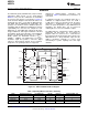
dc accuracy and superior ac performance. Figure 57 In High-Speed mode, the maximum data rate is
shows the block diagram. Note that both devices are 144kSPS. In High-Resolution mode, the SNR =
functionally the same, except that the ADS1274 has 111dB (V
REF
= 3.0V); in Low-Power mode, the power
four ADCs and the ADS1278 has eight ADCs. The dissipation is 31mW/channel; and in Low-Speed
packages are identical, and the ADS1274 pinout is mode, the power dissipation is only 7mW/channel at
compatible with the ADS1278, permitting true drop-in 10.5kSPS. The digital filters can be bypassed,
expandability. The converters are comprised of four enabling direct access to the modulator output.
(ADS1274) or eight (ADS1278) advanced, 6th-order,
The ADS1274/78 is configured by simply setting the
chopper-stabilized, delta-sigma modulators followed
appropriate I/O pins—there are no registers to
by low-ripple, linear phase FIR filters. The modulators
program. Data are retrieved over a serial interface
measure the differential input signal, V
IN
= (AINP –
that supports both SPI and Frame-Sync formats. The
AINN), against the differential reference, V
REF
=
ADS1274/78 has a daisy-chainable output and the
(VREFP – VREFN). The digital filters receive the
ability to synchronize externally, so it can be used
modulator signal and provide a low-noise digital
conveniently in systems requiring more than eight
output. To allow tradeoffs among speed, resolution,
channels.
and power, four operating modes are supported:
(1) The ADS1274 has four channels; the ADS1278 has eight channels.
Figure 57. ADS1274/ADS1278 Block Diagram
Table 2. Operating Mode Performance Summary
MODE MAX DATA RATE (SPS) PASSBAND (kHz) SNR (dB) NOISE (μV
RMS
) POWER/CHANNEL (mW)
High-Speed 144,531 65,472 106 8.5 70
(1)
High-Resolution 52,734 23,889 110 5.5 64
Low-Power 52,734 23,889 106 8.5 31
Low-Speed 10,547 4,798 107 8.0 7
(1) Specified at 105kSPS.
20 Submit Documentation Feedback © 2007–2011, Texas Instruments Incorporated
Product Folder Link(s): ADS1274 ADS1278