
Datasheet

Setup
September 2012 TPS54362EVM User’s Guide 5
2.3. Operation
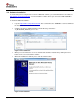
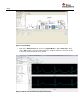
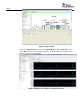
The figure below shows the connection between the ADS1293EVM and a personal computer with the
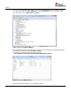
ADS1293’s software. The figures below show both the top and bottom of the board. For proper operation of
the ADS1293EVM, J3 and J4 should be properly configured.
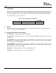
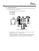
For this quick start, connect the following jumpers:
Jumper pins 1 & 2 of JP2 to connect VDD to 3.3V
Jumper pins 1 & 2 of JP3 to connect VDDIO to 3.3V
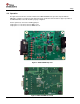
Figure 5: ADS1293EVM Top View
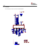
Figure 6: ADS1293VM Bottom View