
Datasheet


MUX[2:0] = 101
TempP
MUX[2:0] = 100
MvddP
(1)
MUX[2:0] = 011
From LoffP
MUX[2:0] = 000
MUX[2:0] = 110
MUX[2:0] = 001
To PgaP
To PgaN
MUX[2:0] = 001
RLDIN
MUX[2:0] = 010
RLD_MEAS
AND
MUX[2:0] = 111
VINP
VINN
MUX[2:0] = 000
From LoffN
RLD_REF
MUX[2:0] = 010
RLD_MEAS
AND
MvddN
(1)
TempN
MUX[2:0] = 100
MUX[2:0] = 101
ADS129x
MUX
TestP
TestN
TESTP_PACE_OUT1
INT_TEST
INT_TEST
TESTN_PACE_OUT2
INT_TEST
INT_TEST
MUX[2:0] = 011
EMI
Filter
(AVDD + AVSS)
2
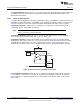
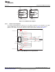
a) Pull-Up/Pull-Down Resistors b) Current Source
PGA
10MW
10MW
AVDD
INP
INN
PGA
AVDD
INP
INN
ADS129xADS129x
www.ti.com
Using the ADS1298ECG-FE Software
Figure 10. Lead-Off Excitation Options
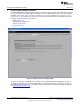
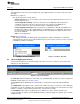
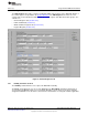
3.4.2.2 Channel Control Registers
The Channel Control Registers box allows the user to uniquely configure the front-end MUX for each ADC
channel. Additionally, at the top of the Channel Control Registers box (see Figure 8) is the option to
globally set all channels to the same setting. The channel-specific MUX is illustrated in Figure 11.
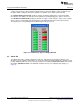
Figure 11. Input Multiplexer for a Single Channel
17
SBAU171C–May 2010–Revised September 2012 ADS1298ECG-FE/ADS1198ECG-FE
Submit Documentation Feedback
Copyright © 2010–2012, Texas Instruments Incorporated