
Datasheet


Using the ADS1298ECG-FE Software
www.ti.com
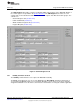
3.4.3 LOFF and RLD Tab (ADC Register)
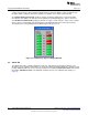
The LOFF and RLD tab provides control over the Lead-Off Detection and Current Control Registers and
the Right Leg Derivation Control Registers. The tab and controls are shown in Figure 12.
Figure 12. LOFF and RLD Tab
3.4.3.1 Lead-Off Detection and Current Direction Control Registers
The first two arrays of controls (Lead Off Sense) enable lead-off detection for both the positive and
negative channels, LOFF_SENSP and LOFF_SENSN. By pressing the buttons, lead-off detection is
enabled for each channel individually and for each input (positive and negative). Set All LOFFP Bits and
Set All LOFFN Bits allow the user to turn on or off all the enable bits at once instead of clicking each
individual channel control.
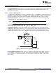
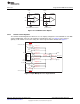
The third array of controls (Lead Off Current Direction) determines the current direction used for lead-off
detection when an excitation signal is selected as a pull-up/pull-down resistor. Each channel is controlled
individually by selecting the button that corresponds to the desired channel to manipulate. When the
button is not illuminated, LOFF_FLIP = 0 (INP is pulled-up to AVDD and INN is pulled-down to ground).
When the button is pressed/illuminated, LOFF_FLIP = 1 (INP is pulled-down to ground and INN is pulled-
up to AVDD). Further details of these registers and lead-off function are located in the Applications
Section of the device data sheet.
18
ADS1298ECG-FE/ADS1198ECG-FE SBAU171C–May 2010–Revised September 2012
Submit Documentation Feedback
Copyright © 2010–2012, Texas Instruments Incorporated