
Datasheet


Wcta
8:1 MUX
WCT1[2:0]
IN4N
IN4P
IN3N
IN3P
IN2N
IN2P
WCT
IN1N
IN1P
Wctb
8:1 MUX
WCT2[5:3]
Wctc
8:1 MUX
WCT2[2:0]
To Channel
PGAs
ADS1294/6/8
30kW 30kW 30kW
80pF
AVSS
Wcta
8:1 MUX
WCT1[2:0]
IN4N
IN4P
IN3N
IN3P
IN2N
IN2P
IN7N
IN7P
IN6N
IN6P
IN5N
IN5P
IN1N
IN1P
Wctb
8:1 MUX
WCT2[5:3]
Wctc
8:1 MUX
WCT2[2:0]
To Channel
PGAs
ADS1298
avF_ch6 avF_ch5 avF_ch7
avF_ch4
To Channel
PGAs
(a) Wilson Central Lead Routing
(b) Wilson Augmented Lead Routing
www.ti.com
Using the ADS1298ECG-FE Software
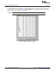
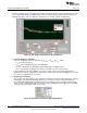
3.4.4.1 Wilson Central and Augmented Lead Registers
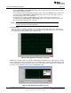
The Wilson Central Voltage (an average voltage between the right arm [RA], left arm [LA], and left leg [LL]
connections) can be derived from any combination of positive and negative terminals from channels 1-4
and routed to the WCT pin. Likewise, the Augmented Leads (AVF, AVL, AVR) may be derived from
channels 1-4 and routed to the negative terminal of channels 5, 6, and 7. Figure 15 shows these
configurations; Figure 15a illustrates the central lead routing, and Figure 15b shows the augmented lead
routing.
Figure 15. Wilson Central and Augmented Lead Routing Diagrams
21
SBAU171C–May 2010–Revised September 2012 ADS1298ECG-FE/ADS1198ECG-FE
Submit Documentation Feedback
Copyright © 2010–2012, Texas Instruments Incorporated