
Datasheet


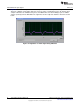


ADS1x98ECG-FE Input Signals
www.ti.com
The voltage used to derive the right leg drive for both the positive and negative electrodes may also be
measured with respect to (AV
DD
+ AV
SS
)/2.
4.6 Lead Derivation
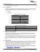
The EVM is configured to generate the 12 ECG signals using 10 electrodes connected to the eight ADC
channels. Lead I, Lead II, and V1-V6 are computed in the analog domain, while the augmented leads and
Lead III are computed digitally. The channel assignments are described in Table 2.
• LA = Left Arm
• LL = Left Leg
• RA = Right Arm
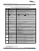
Table 2. ADS1298 Lead Measurements
ADS1298 Input Channels Lead
(1)
1 V6 = V6 – WCT
2 LEAD I = LA – RA
3 LEAD II = LL – RA
4 V2 = V2 – WCT
5 V3 = V3 – WCT
6 V4 = V4 – WCT
7 V5 = V5 – WCT
8 V1 = V1 – WCT
(1)
WCT = (LA + RA + LL)/3
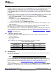
Table 3. Derived Lead Calculations
Derived Lead Formula Used to Calculate
LEAD III LL - RA - LA = LEAD II - LEAD I
aVR RA - (LA + LL) / 2 = - (LEAD I + LEAD II) / 2
aVL LA - (RA +LL) / 2 = LEAD I - LEAD II / 2
aVF LL - (RA + LA) / 2 = LEAD II - LEAD I /2
4.7 Wilson Center Terminal (WCT)
The Wilson Center Terminal voltage is internally generated by the ADS1298 device. The WCT1 and
WCT2 registers provide controls to select any of the eight inputs (CH1P to CH4P, CH1M to CH4M) for
routing to the three integrated WCT amplifiers.
The ADS1298ECG-FE is configured for 12-lead ECG inputs, with the limb electrodes connected as shown
in Table 2. During EVM power-up, the firmware configures the device to route CH2P, CH2M, and CH3P
(RA, LA, LL) to the internal buffers. This configuration generates a signal at the WCT pin equal to (RA +
LA + LL)/3. By installing JP16, the WCT is routed to the single-ended channels to achieve the desired
signals.
4.8 Right Leg Drive
The RL electrode is driven directly by the RLD signal generated on-chip by the ADS1298. The bandwidth
of the RLD loop is determined by R8 (392kΩ) and C20 (10nF). Users can change these values to set the
bandwidth based on their specific application. The loop stability is determined by the user’s specific
system. Therefore, adjustment of the feedback component values may be required to ensure stability if
additional filtering components and long cables are added before the ADS1298ECG-FE.
In a typical application, the RLD signal is implemented as the average of RA, LA, and LL. For system
flexibility, the ADS1298 allows the user to select any combination of the electrodes to generate the RLD
(see ADS1298 data sheet or ADS1198 data sheet for more details).
36
ADS1298ECG-FE/ADS1198ECG-FE SBAU171C–May 2010–Revised September 2012
Submit Documentation Feedback
Copyright © 2010–2012, Texas Instruments Incorporated