
Datasheet


ADS1298ECG-FE/ADS1198ECG-FE Hardware Details
www.ti.com
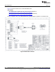
5.7.1 Patient Simulator Input
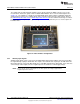
The output from any typical patient simulator can be directly fed into the DB15 connector (J1). For all
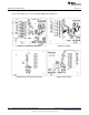
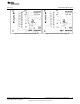
measurements in this user guide, a Fluke medSim 300B simulator was used as the ECG signal source
(Figure 37) . The simulator is capable of generating ECG signals down to 50µV of amplitude. Particular
attention must be given to the common-mode value of the input signal for proper data capture. Refer to
the ADS1298 product data sheet or ADS1198 product data sheet for the common-mode range for various
programmable gain amplifier (PGA) gain settings. Section 4.4.1 explains the process used to capture 12-
lead ECG data.
Figure 37. Fluke Simulator Configuration
5.7.2 Arbitrary Input Signals
Arbitrary input signals can be connected to the ADS1298 by bypassing the DB15 connector and feeding
the signal directly at jumpers JP26-JP33. This requires the removal of the 16 jumpers at JP26-JP33. The
input signal must be connected differentially since each ADC channel input is differential. If it is desired to
connect single-ended signals, bias the negative input of the channels to a mid-supply voltage.
NOTE: Ensure that the single-ended signal has an offset equal to the voltage supplied at the
negative input of the channel.
44
ADS1298ECG-FE/ADS1198ECG-FE SBAU171C–May 2010–Revised September 2012
Submit Documentation Feedback
Copyright © 2010–2012, Texas Instruments Incorporated