User's Guide SBAU162A – December 2009 – Revised September 2010 ADS1675REF ADS1675REF This user's guide describes the characteristics, operation, and use of the ADS1675REF reference design board. This reference design board (REF) is an evaluation platform for the ADS1675, a 4MSPS, high-speed, high-precision, 24-bit analog-to-digital converter (ADC). The ADS1675REF allows evaluation of all aspects of the ADS1675 device.
Preface 1 2 3 4 5 6 7 8 www.ti.com Contents Preface ....................................................................................................................... 2 Overview ..................................................................................................................... 3 Power-Supply Requirements .............................................................................................. 4 Analog Interface ..................................................................
Overview www.ti.com 2 Overview 2.
Power-Supply Requirements www.ti.com The SDRAM controller code is preloaded within the FPGA. The ADCPro software works with the USB 2.0 driver in the ADS1675REF environment, so that 8M, 24-bit sampled ADC data can be captured and saved in the SDRAM per single acquisition in order to allow the FPGA processor to do post-data processing or transfer the test data continually through the FPGA, SDRAM, and USB interface into a PC processor for further data processing.
Analog Interface www.ti.com 3.2 Analog +5V Supply The ADS1675REF board requires an independent analog +5V supply to power the analog portion of the device under test, the external reference, and the external reference buffer, as well as provide the amplifier common-mode voltage. This voltage is applied to J5 pin 3 and is denoted as +5VA. This supply can be monitored at TP7. 3.
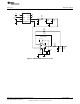
Digital Interface www.ti.com To maximize the dynamic range of the THS4503 and reduce the THD impact from this amplifier, +9V and –4V are used for this THS4503. This configuration gives a maximum ±6.5V swing range. Figure 1 illustrates the typical analog input section of the ADS1675REF. C12 Not Installed R13 249W +VCC Not Installed VSC72 C38 10mF C37 0.
Reference Voltage www.ti.com Figure 2 shows the ADS1675REF reference circuit. +5VA C10 1mF 1 DNC DNC 8 2 VIN N/C 7 3 TEMP OUT 6 4 GND TRIM 5 REF5030AID R21 1kW C21 1 mF C20 10mF C19 0.1mF C15 1mF R22 49.9W C22 0.15mF OPA211AIDGK 4 2 R25 100W 5 6 3 7 8 1 C30 0.1mF C48 1mF C47 10mF C46 10mF +5VA Figure 2.
ADS1675REF Plug-in Operation 7 www.ti.com ADS1675REF Plug-in Operation This section provides information on using the ADS1675REF Plug-in, including setup, program installation, and program usage. The board is factory-configured for the analog input driver THS4503 with +9V and –4V supplies and the shared analog, digital, and XEM3010 board with a +5VA supply on the ADS1675. Table 2 lists the default jumper setup. Table 2.
ADS1675REF Plug-in Operation www.ti.com The software should now be installed, but the USB drivers may not have been loaded by the PC operating system. The USB driver upload step completes when the ADCPro software is executed (see Section 7.2, Running the Software and Completing the Driver Installation). 7.2 Running the Software and Completing the Driver Installation NOTE: The software is continually under development.
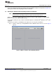
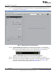
ADS1675REF Plug-in Operation space Step 2. www.ti.com Select ADS1675REF from the REF drop-down menu. The ADS1675REF plug-in appears in the left pane, as shown in Figure 4. Figure 4. ADS1675REF Plug-in Display Window Step 3. The ADS1675REF plug-in window has a status area at the top of the screen. When the plug-in is first loaded, the plug-in searches for the board. You will see a series of messages in the status area that indicate this action, such as Connected (as Figure 5 illustrates). Figure 5.
ADS1675REF Plug-in Operation www.ti.com Figure 6. XEM3010 Driver Installation (Screen 1) Figure 7.
ADS1675REF Plug-in Operation www.ti.com Figure 8. XEM3010 Driver Installation (Screen 3) Figure 9. XEM3010 Driver Installation (Screen 4) Step 6. Step 7. Step 8. When Windows installs the software driver, the plug-in downloads the firmware to the XEM3010. Windows will display the installation wizard a second time. Again, accept the default settings. The status area displays a connected message. The software is now ready to use.
ADS1675REF Plug-in Operation www.ti.com 7.3 Evaluating with the ADCPro Software The evaluation software is based on ADCPro, a program that operates using a variety of plug-ins. To use ADCPro, you must load both a REF plug-in and a test plug-in. To load a REF plug-in, select it from the REF menu. To load a test plug-in, select it from the Test menu. To unload a plug-in, select the Unload option from the corresponding menu. Only one of each type of plug-in (REF and Test) can be loaded at a time.
ADS1675REF Plug-in Operation www.ti.com Figure 12. Six Default Data Rates for LVDS Figure 13. Four Default Data Rates for CMOS Choose a test to run from the Test menu. In the example shown in Figure 14, the MultiFFT test was chosen. Figure 14.
Schematic and Bill of Materials www.ti.com Press the Acquire button. Depending on the size of the sample set captured and the speed for which the ADS1675 is configured, the time required to display the data in the screen varies. Figure 15 shows the results of a 1MSPS sample rate in CMOS mode with the wide-bandwidth filter selected. Figure 15.
Schematic and Bill of Materials 8.1 www.ti.com Bill of Materials NOTE: All components should be compliant with the European Union Restriction on Use of Hazardous Substances (RoHS) Directive. Some part numbers may be either leaded or RoHS. Verify that purchased components are RoHS-compliant. (For more information about TI's position on RoHS compiance, see the Quality and Eco-Info information on the TI web site.) Table 3.
Schematic and Bill of Materials www.ti.com Table 3. ADS1675REF Bill of Materials (continued) Item Quantity Value Reference Designators Description MFR Part Number 38 7 TP1, TP2, TP3, TP5, TP7, TP9, Test Point PC Mini .040"D Red TP11 39 4 TP4, TP6, TP8, TP10 Test Point PC Mini .040"D Black Keystone 5001 40 1 U1 IC Prec V-REF 2.5V LN 8-SOIC TI REF5025ID 41 1 U2 IC Prec V-REF 3.
Revision History www.ti.com Revision History Changes from Original (December, 2009) to A Revision ............................................................................................... Page • • • Updated Bill of Materials ............................................................................................................... 16 Changed Figure 16 to show Revision B of the board ..............................................................................
1 2 3 4 6 5 Revision History REV ECN Number Approved D D RCM +VCC R11 NI J3 R12 -IN R16 NI R10 0 249 C12 R13 C6 NI 249 C72 NI +VCC C38 C37 NI 10uF 0.1uF Vs- 3 R4 NI R7 7 R1 NI NI 8 Vs+ PD* U3 C C 5 Vin+ RCM R18 0 R20 10 VOUT- 2 THS4503ID COM 750pF VOUT+ 1 4 Vin- R17 0 R19 10 AINP Vs- R44 80.5 AINN C17 6 Vs-VCC RCM +VCC R8 J1 R5 C39 10uF 0.
1 2 3 4 6 5 Revision History REV ECN Number Approved +5VD D +5VA 1 2 C10 1uF 3 DNC DNC VIN N/C TEMP 4 GND OUT TRIM 8 C70 C71 0.1uF 4.7uF D U6 7 1 R21 6 5 C15 U2 REF5030AID 1k 4 C21 C20 C19 1uF 10uF 0.1uF 3 A Vcc Y B 5 2 FPGA_CLK GND R40 SN74AHC1G32DRL 1uF 49.9 +5VD C32 C27 10uF C73 1uF 0.1uF C26 R22 49.9 C22 4.7pF C33 C53 4.7uF 0.1uF +5VA +3.3VD 0.15uF C29 C50 4.7uF OPA211AIDGK C52 C35 C54 0.1uF 4.7uF 0.
1 2 3 4 6 5 Revision History REV ECN Number Approved FPGA_CLK +5VD /DRDY R32 D +3.3VD JP4 D JP2 J6 R29 100 /DOUT SCLK R31 100 C /SCLK +5VA R39 +5VD 0 +5VD J9 L5 1 2 TP3 C59 C65 0.
Evaluation Board/Kit Important Notice Texas Instruments (TI) provides the enclosed product(s) under the following conditions: This evaluation board/kit is intended for use for ENGINEERING DEVELOPMENT, DEMONSTRATION, OR EVALUATION PURPOSES ONLY and is not considered by TI to be a finished end-product fit for general consumer use. Persons handling the product(s) must have electronics training and observe good engineering practice standards.
IMPORTANT NOTICE Texas Instruments Incorporated and its subsidiaries (TI) reserve the right to make corrections, modifications, enhancements, improvements, and other changes to its products and services at any time and to discontinue any product or service without notice. Customers should obtain the latest relevant information before placing orders and should verify that such information is current and complete.