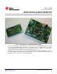
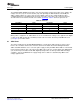
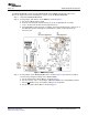
User's Guide SBAU140 – December 2008 MSOP-8EVM and MSOP-8EVM-PDK Figure 1. MSOP-8EVM (Left) and MSOP-8EVM-PDK (Right) This user's guide describes the characteristics, operation, and use of the MSOP-8EVM, both by itself and as part of the MSOP-8EVM-PDK. This EVM is an evaluation board for single-channel, 14- to 16-bit, analog-to-digital converter (ADC) devices in an MSOP-8 package. A complete circuit description, schematic diagram, and bill of materials are included with this document.
www.ti.com Contents 1 EVM Overview ............................................................................................................... 3 2 Analog Interface.............................................................................................................. 4 3 Digital Interface .............................................................................................................. 4 4 Power Supplies .................................................................................
EVM Overview www.ti.com 1 EVM Overview 1.1 Features MSOP-8EVM Features: • Full-featured evaluation board for a variety of single-channel, 8-pin, micro-SOP, 14- to 16-bit, serial output, ADCs • Onboard reference and buffer circuits • High-speed serial interface • Modular design for use with a variety of DSP and microcontroller interface boards For use with a computer, the MSOP-8EVM-PDK is available.
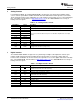
Analog Interface 2 www.ti.com Analog Interface For maximum flexibility, the modular MSOP-8EVM is designed for easy interfacing to multiple analog sources. Samtec part numbers SSW-110-22-F-D-VS-K and TSM-110-01-T-DV-P provide a convenient, 10-pin, dual-row header/socket combination at J1. This header/socket provides access to the analog input pins of the ADC. Consult Samtec at http://www.samtec.com or call 1-800-SAMTEC-9 for a variety of mating connector options. Table 2.
Power Supplies www.ti.com 4 Power Supplies The modular MSOP-8EVM board requires +5V dc for the analog section. This power source supplies the voltage reference (U2), the reference buffer (U4), and optionally, the ADC installed on the EVM (via JMP1). Supply voltages of +1.8V to +5V dc for the digital section are also required. When used in combination with one of the DAP Interface boards, J3 provides connection to the common power bus described in the 5-6 K Interface Board User's Guide, (SLAU104).
Power Supplies 4.2 www.ti.com Standalone Operation When used as a standalone EVM, the analog power can be applied to TP5 and referenced to TP6. Digital power can be applied to TP7, referenced to TP4. While filters are provided for all power-supply inputs, optimal performance of the EVM requires a clean, well-regulated power source. CAUTION The ADCs that are compatible with this EVM have a variety of power-supply requirements.
EVM Operation www.ti.com 5 EVM Operation This section provides information on the analog input, digital control, and general operating conditions of the MSOP-8EVM. 5.1 Analog Input The analog input source can be applied directly to J1 (top or bottom side) or through optional amplifier and signal conditioning modules. The analog input range depends on the configuration of the EVM and the ADC installed at location U1. Consult the specific device data sheet to determine the maximum analog input range. 5.
MSOP-8EVM-PDK Kit Operation 6 www.ti.com MSOP-8EVM-PDK Kit Operation This section provides information on using the MSOP-8EVM-PDK, including setup, program installation, and program usage. To prepare Step 1. Step 2. Step 3. Step 4. Step 5. Step 6. to evaluate the MSOP-8EVM with the MSOP-8EVM-PDK, complete the following steps: Install the ADCPro software (if not already installed). Install the MSOP-8EVM-PDK EVM plug-in software. Set up the MSOP-8EVM-PDK.
MSOP-8EVM-PDK Kit Operation www.ti.com 6.2 Setting Up the MSOP-8EVM-PDK The MSOP-8EVM-PDK contains both the MSOP-8EVM and the MMB0 motherboard; however, the devices are shipped unconnected. Follow these steps to set up the MSOP-8EVM-PDK: Step 1. Unpack the MSOP-8EVM-PDK kit. Step 2. Set the jumpers and switches on the MMB0 as shown in Figure 2. a. Set the Boot Mode switch to USB. b. Connect +5V and +5VA on jumper block J13 (if +5V is supplied from J14 +5VA). c.
MSOP-8EVM-PDK Kit Operation www.ti.com Figure 3. MSOP-8 EVM Board Initial Setup Step 4. Plug the MSOP-8EVM into the MMB0. Figure 4. Connecting the MSOP-8EVM to the MMB0 Motherboard CAUTION Do not misalign the pins when plugging the MSOP-8EVM into the MMB0. Check the pin alignment of J1, J2 and J3 carefully before applying power to the PDK. 6.2.1 About the MMB0 The MMB0 is a modular EVM system motherboard.
MSOP-8EVM-PDK Kit Operation www.ti.com 6.3 Connecting the Power Supply The MSOP-8EVM-PDK can be operated with a unipolar +5V supply, in which case an ac adapter or a lab power supply can be used. When the MMB0 DSP is powered properly, LED D2 glows green. The green light indicates that the 3.3V supply for the MMB0 is operating properly; however, it does not indicate that the EVM power supplies are operating properly. 6.3.
MSOP-8EVM-PDK Kit Operation 6.3.2 www.ti.com Connecting a Laboratory Power Supply A laboratory power supply can be connected through terminal block J14 on the MMB0, as shown in Figure 6. To use a unipolar lab power supply configuration: • Disconnect J12 on the MMB0. • Connect a +5V dc supply to the +5VD terminal on J14. • Connect ground of the dc supply to the GND terminal on J14.
MSOP-8EVM-PDK Kit Operation www.ti.com 6.4 Running the Software and Completing Driver Installation Note: The software is continually under development. These instructions and screen images are current at the time of this writing, but may not exactly match future releases. The program for evaluating the MSOP-8EVM-PDK is called ADCPro. This program uses plug-ins to communicate with the EVM. The MSOP-8EVM-PDK plug-in is included in the MSOP-8EVM-PDK package. The program currently runs only on Windows XP.
MSOP-8EVM-PDK Kit Operation Step 2. www.ti.com Select ADSXXXXEVM (where ADSXXXXEVM is the installed device which is to be evaluated) from the EVM drop-down menu. The ADSXXXXEVM-PDK plug-in appears in the left pane, as shown in Figure 8. Figure 8. ADS8326EVM-PDK Plug-In Display Window Step 3. Step 4. Step 5. 14 The MSOP-8EVM-PDK plug-in window has a status area at the top of the screen. When the plug-in is first loaded, the plug-in searches for the board.
MSOP-8EVM-PDK Kit Operation www.ti.com Figure 9. Found New Hardware Wizard, Screen 1 Figure 10.
MSOP-8EVM-PDK Kit Operation www.ti.com Figure 11. Found New Hardware Wizard, Screen 3 Figure 12.
MSOP-8EVM-PDK Kit Operation www.ti.com Figure 13. Found New Hardware Wizard, Screen 5 Step 6. Step 7. Step 8. When Windows installs the software driver, the plug-in downloads the firmware to the MMB0. Windows will display the installation wizard a second time. Again, accept the default settings. The status area displays a connected message. The software is now ready to use. The driver installation wizard sequence should not appear again, unless you connect the board to a different USB port.
Evaluating with the ADCPro Software 7 www.ti.com Evaluating with the ADCPro Software The evaluation software is based on ADCPro, a program that operates using a variety of plug-ins. (The MSOP-8EVM plug-in is installed as described in the installation section.) To use ADCPro, load an EVM plug-in and a test plug-in. To load an EVM plug-in, select it from the EVM menu. To load a test plug-in, select it from the Test menu. To unload a plug-in, select the Unload option from the corresponding menu.
Evaluating with the ADCPro Software www.ti.com 7.1.2 Clockstop Mode—Max SCLK In this mode, SCLK frequency is also the highest possible serial clock frequency for the data converter under test. The sampling frequency can be adjusted to any desired rate by entering a value in the sampling rate window. The primary difference in this mode of operation is that there are 24 cycles of the serial clock applied to the ADC while the CS input is active.
Evaluating with the ADCPro Software 7.1.4 www.ti.com Collecting Data Once you have configured the ADSXXXXEVM device for your test scenario, pressing the ADCPro Acquire button starts the collection of the number of data points specified in the Test plug-in Block Size control. The ADSXXXXEVM-PDK plug-in disables all the front panel controls while acquiring and displays a progress bar, as shown in Figure 17. Figure 17.
Appendix A www.ti.com Appendix A Bill of Materials (BOM) and Schematic Table A-1 contains a complete bill of materials for the modular MSOP-8EVM. The schematic diagram is also provided. Table A-1. Bill of Materials Designators Description Manufacturer Mfg. Part Number C2, C3, C4, C13 Not Installed R11 Not Installed C1 0.47µF, 0805, Ceramic, X7R, 10% Panasonic ECJ-2YB1C474K C11, C12, C14 0.
1 2 3 4 Revision History REV ECN Number B Approved Initial Release TH +5Va C1 0.47uF D D 1 +LVa JMP1 VIN C11 0.1uF 2 GND JMP5 U4 3 4 SCLK JMP6 R12 1 REF3025 C10 10uF J2 +V(adc) 5 OUT 3 +5Va +5Va U2 JMP2 22.1 VREF R10 33 R6 0 ohm /CS 2 OPA353N C6 10uF IN- C3 NI 8 +Vcc 5 C13 NI SN74LVC1G125 +V(i/o) JMP4 B 5 REFREF+ SDO 3 3 0 ohm C12 0.
EVALUATION BOARD/KIT IMPORTANT NOTICE Texas Instruments (TI) provides the enclosed product(s) under the following conditions: This evaluation board/kit is intended for use for ENGINEERING DEVELOPMENT, DEMONSTRATION, OR EVALUATION PURPOSES ONLY and is not considered by TI to be a finished end-product fit for general consumer use. Persons handling the product(s) must have electronics training and observe good engineering practice standards.
IMPORTANT NOTICE Texas Instruments Incorporated and its subsidiaries (TI) reserve the right to make corrections, modifications, enhancements, improvements, and other changes to its products and services at any time and to discontinue any product or service without notice. Customers should obtain the latest relevant information before placing orders and should verify that such information is current and complete.