
Datasheet

User's Guide
SLAU298–November 2009
ADS855xEVM
This users guide describes the characteristics, operation, and use of the ADS855xEVM 16/14/12-bit
parallel analog to digital converter Evaluation Board. A complete circuit description as well as schematic
diagram and bill of materials is included.
Contents
1 EVM Overview ............................................................................................................... 2
1.1 Features ............................................................................................................. 2
1.2 Introduction ......................................................................................................... 2
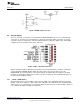
1.3 Analog Interface .................................................................................................... 2
2 Digital Interface .............................................................................................................. 4
2.1 Digital Power – Buffer I/O Supply ................................................................................ 4
2.2 Control Signals ..................................................................................................... 5
3 Power Supplies .............................................................................................................. 7
4 EVM Operation .............................................................................................................. 7
4.1 Analog Inputs – J2 ................................................................................................. 8
4.2 Digital Controls – J1, J4 and J5 .................................................................................. 8
5 Related Documentation from Texas Instruments ....................................................................... 9
6 Bill of Materials, Top Level Silkscreen and Schematic ............................................................... 10
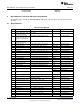
6.1 Bill of Materials .................................................................................................... 10
6.2 Top Level Silkscreen ............................................................................................. 12
6.3 Schematic ......................................................................................................... 12
List of Figures
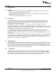
1 ADS855xEVM Schematic – Typical Analog Input Section ............................................................ 3
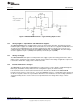
2 ADS855xEVM External Reference Circuit............................................................................... 4
3 BVDD Voltage Selection ................................................................................................... 5
4 SW1 – Operational Controls............................................................................................... 5
5 ADS855xEVM Silk Screen Drawing .................................................................................... 12
List of Tables
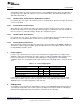
1 J3 – Power Supply Inputs.................................................................................................. 7
2 Factory Jumper Defaults ................................................................................................... 8
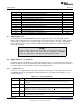
3 J1 – Serial Control Inputs .................................................................................................. 8
4 J4 – Parallel Control ........................................................................................................ 9
5 J4 – Parallel Control ........................................................................................................ 9
6 Bill of Materials............................................................................................................. 10
1
SLAU298–November 2009 ADS855xEVM
Submit Documentation Feedback
Copyright © 2009, Texas Instruments Incorporated