
Datasheet


SLLS104I − DECEMBER 1990 − REVISED SEPTEMBER 2004
5
POST OFFICE BOX 655303 • DALLAS, TEXAS 75265
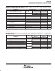
electrical characteristics over recommended ranges of V
CC
, V
IC
, and operating free-air
temperature (unless otherwise noted)
PARAMETER TEST CONDITIONS MIN TYP
†
MAX UNIT
V
IT+
Differential input high-threshold voltage
V
O
= V
OH
(min),
V
IC
= −7 V to 7 V 0.2
V
V
IT+
Differential input high-threshold voltage
V
O
= V
OH
(min),
I
OH
= −440 µA
V
IC
= 0 to 5.5 V 0.1
V
V
IT−
Differential input low-threshold voltage
V
O
= 0.45 V,
V
IC
= −7 V to 7 V −0.2
‡
V
V
IT−
Differential input low-threshold voltage
V
O
= 0.45 V,
I
OL
= 8 mA
V
IC
= 0 to 5.5 V −0.1
‡
V
V
hys
Hysteresis voltage (V
IT+
− V
IT−
) 60 mV
V
IK
Enable input clamp voltage V
CC
= 4.5 V, I
I
= −18 mA −1.5 V
V
OH
High-level output voltage V
ID
= 200 mV, I
OH
= −6 mA 3.8 V
V
OL
Low-level output voltage V
ID
= −200 mV, I
OL
= 6 mA 0.2 0.3 V
I
OZ
Off-state (high-impedance state) output current V
O
= V
CC
or GND ±0.5 ±5 µA
I
I
Line input current
V
I
= 10 V, Other input at 0 V 1.5
mA
I
I
Line input current
V
I
= −10 V,
Other input at 0 V −2.5
mA
I
IH
High-level enable current V
I
= 2.7 V 20 µA
I
IL
Low-level enable current V
I
= 0.4 V −100 µA
r
i
Input resistance One input to ground 12 17 kΩ
I
CC
Supply current V
CC
= 5.5 V 10 15 mA
†
All typical values are at V
CC
= 5 V, V
IC
= 0, and T
A
= 25°C.
‡
The algebraic convention, in which the less positive (more negative) limit is designated minimum, is used in this data sheet for common-mode
input voltage.
switching characteristics over recommended ranges of operation conditions, C
L
= 50 pF (unless
otherwise noted)
PARAMETER
TEST
CONDITIONS
AM26C32C
AM26C32I
AM26C32Q
AM26C32M
UNIT
PARAMETER
CONDITIONS
MIN TYP
†
MAX MIN TYP
†
MAX
UNIT
t
PLH
Propagation delay time, low- to high-level output
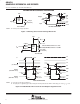
See Figure 1
9 17 27 9 17 27 ns
t
PHL
Propagation delay time, high- to low-level output
See Figure 1
9 17 27 9 17 27 ns
t
TLH
Output transition time, low- to high-level output
See Figure 1
4 9 4 10 ns
t
THL
Output transition time, high- to low-level output
See Figure 1
4 9 4 9 ns
t
PZH
Output enable time to high level
See Figure 2
13 22 13 22 ns
t
PZL
Output enable time to low level
See Figure 2
13 22 13 22 ns
t
PHZ
Output disable time from high level
See Figure 2
13 22 13 26 ns
t
PLZ
Output disable time from low level
See Figure 2
13 22 13 25 ns
†
All typical values are at V
CC
= 5 V, T
A
= 25°C.