
Datasheet


www.ti.com
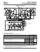
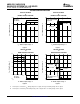
PARAMETER MEASUREMENT INFORMATION
Waveform 1
(see Note E)
Output Z
Output Y
Input A
(see Notes B
and C)
V
OL
V
OH
V
OL
V
OH
3 V
t
PHL
Skew Skew
t
PLH
t
PLH
t
PHL
0 V
PROPAGATION DELAY TIMES AND SKEW TEST CIRCUIT
V
CC
Test Point
S1
S2
75 Ω
180 Ω
C
L
(see Note A)
From Output
Under Test
V
OH
V
OL
≈1.5 V
0 V
3 V
Enable G
Enable G
(see Note D)
S1 Open
S2 Closed
S1 Closed
S2 Open
t
PZH
t
PZL
t
PHZ
t
PLZ
S1 Closed
S2 Closed
0.5 V
≈0 V
≈4.5 V
S1 Closed
S2 Closed
≈1.5 V
ENABLE AND DISABLE TIME WAVEFORMS
See Note D
NOTES: A. C
L
includes probe and jig capacitance.
B. All input pulses are supplied by generators having the following characteristics: PRR ≤ 1 MHz, Z
O
≈ 50 Ω, t
r
≤ 15 ns, t
f
≤ 6 ns.
C. When measuring propagation delay times and skew, switches S1 and S2 are open.
D. Each enable is tested separately.
E. Waveform 1 is for an output with internal conditions such that the output is low, except when disabled by the output control.
Waveform 2 is for an output with internal conditions such that the output is high, except when disabled by the output control.
1.3 V 1.3 V
1.5 V
1.5 V
1.5 V 1.5 V
Waveform 2
(see Note E)
0.5 V
1.5 V
1.5 V
AM26LS31C , AM26LS31M
QUADRUPLE DIFFERENTIAL LINE DRIVER
SLLS114I – JANUARY 1979 – REVISED FEBRUARY 2006
Figure 1. Test Circuit and Voltage Waveforms
5
Submit Documentation Feedback