
Datasheet


AMC1100
www.ti.com
SBAS562 –APRIL 2012
REGULATORY INFORMATION
VDE AND IEC UL
Certified according to IEC 60747-5-2 Recognized under 1577 component recognition program
File number: 40016131 File number: E181974
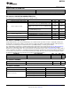
IEC 60747-5-2 INSULATION CHARACTERISTICS
Over operating free-air temperature range, unless otherwise noted.
PARAMETER TEST CONDITIONS VALUE UNIT
V
IORM
Maximum working insulation voltage 1200 V
PEAK
Qualification test: after input/output safety test subgroup
1140 V
PEAK
2/3 V
PR
= V
IORM
× 1.2, t = 10 s, partial discharge < 5 pC
Qualification test: method A, after environmental tests
V
PR
Input-to-output test voltage subgroup 1, V
PR
= V
IORM
× 1.6, t = 10 s, partial discharge 1920 V
PEAK
< 5 pC
100% production test: method B1, V
PR
= V
IORM
× 1.875,
2250 V
PEAK
t = 1 s, partial discharge < 5 pC
V
IOTM
Transient overvoltage Qualification test: t = 60 s 4250 V
PEAK
Qualification test: V
TEST
= V
ISO
, t = 60 s 4250 V
PEAK
V
ISO
Insulation voltage per UL
100% production test: V
TEST
= 1.2 x V
ISO
, t = 1 s 5100 V
PEAK
R
S
Insulation resistance V
IO
= 500 V at T
S
> 10
9
Ω
PD Pollution degree 2 °
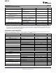
IEC SAFETY LIMITING VALUES
Safety limiting intends to prevent potential damage to the isolation barrier upon failure of input or output (I/O) circuitry. I/O
circuitry failure can allow low resistance to either ground or supply and, without current limiting, dissipate sufficient power to
overheat the die and damage the isolation barrier, thus potentially leading to secondary system failures.
The safety-limiting constraint is the operating virtual junction temperature range specified in the Absolute Maximum Ratings
table. The power dissipation and junction-to-air thermal impedance of the device installed in the application hardware
determine the junction temperature. The assumed junction-to-air thermal resistance in the Thermal Information table is that of
a device installed in the JESD51-3, Low Effective Thermal Conductivity Test Board for Leaded Surface-Mount Packages and
is conservative. The power is the recommended maximum input voltage times the current. The junction temperature is then
the ambient temperature plus the power times the junction-to-air thermal resistance.
PARAMETER TEST CONDITIONS MIN TYP MAX UNIT
I
S
Safety input, output, or supply current θ
JA
= 246°C/W, V
IN
= 5.5 V, T
J
= +150°C, T
A
= +25°C 10 mA
T
C
Maximum-case temperature +150 °C
IEC 61000-4-5 RATINGS
PARAMETER TEST CONDITIONS VALUE UNIT
V
IOSM
Surge immunity 1.2-μs or 50-μs voltage surge and 8-μs or 20-μs current surge ±6000 V
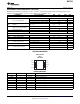
IEC 60664-1 RATINGS
PARAMETER TEST CONDITIONS SPECIFICATION
Basic isolation group Material group II
Rated mains voltage ≤ 150 V
RMS
I-IV
Rated mains voltage ≤ 300 V
RMS
I-IV
Installation classification
Rated mains voltage ≤ 400 V
RMS
I-III
Rated mains voltage < 600 V
RMS
I-III
Copyright © 2012, Texas Instruments Incorporated Submit Documentation Feedback 3
Product Folder Link(s): AMC1100