
Datasheet

www.ti.com
Remote Temperature Sensor Failure Detection
PWM Output
+5V
PWM-Out
ON
PWM
Control
AMC6821
PWM-EN
PWMINV=1fordrivingtheNMOS.
+5V
PWM-Out
ON
PWM
Control
AMC6821
PWM-EN
PWMINV=0(default)fordrivingthePMOS.
PWMINV=0
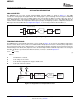
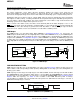
PWM WAVEFORM SETTING
RPMreducesasthe
duty cycledecreases.
Period
ON
OFF
AMC6821
SBAS386C – MAY 2006 – REVISED JULY 2007
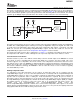
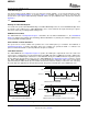
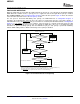
The remote temperature sensor failure detection determines whether the remote sensor diode has an
open-circuit condition, a short-circuit to ground, or a short-circuit (IN+) to (IN – ) condition. This fault detection is
based on the analog input voltage and is not checked until the first monitoring cycle is completed after power-on.
Reading the fault sensor returns a value of – 128 ° C (0x80). Since the power-on default value of the temperature
data registers is 0x80 ( – 128 ° C), a reading of 0x80 from the temperature data register immediately after power-on
does not indicate a diode fault condition. The remote temperature sensor failure is only checked after the first
monitoring cycle has been completed after power-on or reset.
When a remote sensor failure occurs, the remote sensor failure bit (RTF in the Status Register) is set to '1', the
OVR pin is forced low, and if the interrupt is enabled (RTFIE = 1), the RTF interrupt is generated through the
SMBALERT pin. Once this interrupt is generated, the RTF bit remains '1' and the OVR pin stays low until a
power-on reset or software reset is issued, whether or not the failure condition persists.
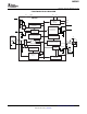
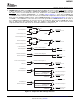
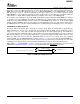
The PWM-Out pin is an open-drain output. When PWM-EN of Configuration Register 2 is cleared ('0'), the
PWM-Out pin is disabled and goes into a high-impedance status. When PWM-EN is set ('1'), the PWM-Out pin is
enabled to drive the fan. When enabled, the status of the PWM-Out pin is determined by the PWM duty cycle
and phase bits (PWMINV of Configuration Register 1 ). When PWMINV = 0 (default), the PWM-Out pin goes low
for 100% duty cycle (suitable for driving the fan using a PMOS FET). Setting PWMINV to '1' makes the PWM-Out
pin go high (with an external pull-up resistor) for a 100% duty cycle. This setting is used to drive an NMOS-power
FET.
Figure 15. PWM Output
PWM frequency and duty cycle are programmable. The value of the DCY Register defines the duty cycle: it has
8-bit resolution, 1LSB corresponding to 1/255 (0.392%). Writing 0x00 sets the duty cycle to 0%; writing 0xFF sets
the duty cycle to 100%.
PWM frequency has two ranges: the high range is from 1kHz to 40kHz, and the low range is from 10Hz to 94Hz.
The PWM-MODE pin status determines which range is selected. When the PWM-MODE pin is tied to ground,
the high range is selected. Otherwise, the low range is selected. Bits [PWM2:PWM0] in the Fan Characteristics
Register define the frequency; see Table 12 . The resolution of the PWM waveform period is 0.312 µ s,
corresponding to a 3.2MHz clock. The default value after power-on is 30Hz when the low range is selected, or
25kHz when the high range is selected.
Figure 16. PWM Waveform (PWMINV = 1)
16 Submit Documentation Feedback Copyright © 2006 – 2007, Texas Instruments Incorporated
Product Folder Link(s): AMC6821