
Datasheet

AMC6821-Q1
www.ti.com
...................................................................................................................................................................................................... SBAS475 – JUNE 2009
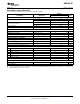
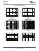
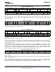
Table 6. Write Multiple Bytes
S SLAVE ADDRESS WR ACK COMMAND ACK DATA ACK DATA ACK
7-bit AMC6821 slave 8-bit register address of First 8-bit data written Second 8-bit data written
address first register to be written first register second register
DATA ACK ... DATA ACK P
Third 8-bit data written third register Last 8-bit data
S = start condition; P = stop condition; shaded = slave to master; unshaded = master to slave; WR = write (bit value of 0).
The first register is the one to which the first data byte is written. The next register is the second register. If the
bus master continues to transfer data into the AMC6821 after writing the last location, all data are ignored until
the operation stops.
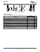
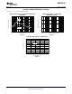
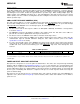
Table 7. Read Byte
S SLAVE ADDRESS WR ACK COMMAND ACK Sr SLAVE ADDRESS RD ACK DATA NACK P
7-bit AMC6821 slave 7-bit AMC6821 slave 8-bit data from
8-bit register address
address address register
S = start condition; P = stop condition; shaded = slave to master; unshaded = master to slave; WR = write (bit value of 0); RD = read (bit
value of 1);
NACK = not acknowledged; Sr = repeated start condition.
Table 8. Read Multiple Bytes
S SLAVE ADDRESS WR ACK COMMAND ACK Sr SLAVE ADDRESS RD ACK DATA ACK
7-bit AMC6821 slave Address of first 7-bit AMC6821 slave 8-bit data from first
address register to be read address register
DATA ACK ... DATA NACK P
8-bit data from second register Last 8-bit data
S = start condition; P = stop condition; shaded = slave to master; unshaded = master to slave; WR = write (bit value of 0); RD = read (bit
value of 1);
NACK = not acknowledged; Sr = repeated start condition.
The first register is the one from which the first data byte is transmitted. The next register is the second register.
If the bus master continues clocking data out after reading the last location (0x3F), the value 0x00 is sent out
until the operation stops.
The AMC6821 is entirely controlled by the registers. All registers are 8-bit. The AMC6821 has an address pointer
register; the value of the address pointer register determines the register to be written to or read from. To write
data to the device register or read data from it, the address pointer register must be set properly. Data can then
be written into or read from that register. The command issued by the bus master always contains the initial
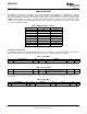
value of the address pointer register. The command is constructed as shown in Table 9 .
Table 9. Command Format
(1)
Bit 7 (MSB) Bit 6 Bit 5 Bit 4 Bit 3 Bit 2 Bit 1 Bit 0 (LSB)
0 0 ADDR5 ADDR4 ADDR3 ADDR2 ADDR1 ADDR0
In the send byte operation, the bus master writes the address of a specified device register into the address
pointer register.
In the receive byte operation, the bus master reads the data back from the device register addressed by the
address point register.
In the write byte operation, the bus master sets the address pointer register to the address of a specified device
register, then writes 8-bit data into it. In the read byte operation, the SMBus master sets the address pointer
register to the address of a specified device register first, then reads 8-bit data back from it.
(1) ADDR[5:0] is the address of the register that is accessed first. The register address is stored in the address pointer register.
Copyright © 2009, Texas Instruments Incorporated Submit Documentation Feedback 9
Product Folder Link(s): AMC6821-Q1