
Stereo Amplifier User Manual


Quick Start
3-2
3.1 Quick Start
Follow these steps to use the APA100 EVM.
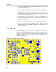
APA100 audio input connection can be made via a phono jack (J1), or by sol-
dering to its pins. The power supply and outputs can be connected with banana
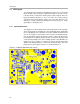
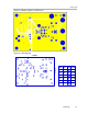
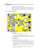
connectors or wires via screw terminals. Figure 3−1 shows numbered callouts
for selected steps.
Figure 3−1. Quick Start Module Map
6
2
5
4
Power Supply
1) Ensure that all external power sources are set to off.
2) Connect an external regulated power supply, set from 18 V to 29.5 V, to
the module A+ (J3) and GND (J4) banana plugs, taking care to observe
marked polarity.
Inputs and Outputs
3) Ensure that the signal source level is set to minimum.
4) Connect the audio source to the input phono connector, J1. The inside of
the phono connector is the audio input, and the outside of the phono con-
nector is ground. Ensure that a single−ended input signal is inserted (NOT
differential or balanced), because the outside of the phono connector is
tied to ground.
5) Connect a 4−Ω or higher impedance speaker to the module OUT+ (J2)
and OUT− (J1) connectors.