
Datasheet

bq2000
2
7
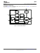
Battery
Pack
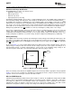
5
TS
N
T
C
V
SS
V
CC
V
CC
R
T1
R
T2
CELLB1
B2 MCV
VR
= N 1
R V
æ ö
´ -
ç ÷
è ø
bq2000
www.ti.com
SLUS138D –JANUARY 2008–REVISED DECEMBER 2009
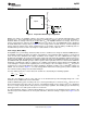
Figure 6. Temperature Monitoring Configuration
During fast charge, the bq2000 compares the battery temperature to an internal high-temperature cutoff
threshold, V
TCO
, and a low-temperature threshold, V
LTF
. During fast charge only, the V
HTF
fault comparator is
disabled. When the voltage at the TS pin is lower than V
TCO
, the bq2000 terminates fast charge, moves to the
charge suspended state, and turns off the LED. When V
TS
rises above V
HTF
, the bq2000 will resume charging in
the trickle maintenance charge state, per Figure 2. In fast charge (either constant current or constant voltage fast
charge), when the voltage on the TS pin is higher than V
LTF
, the charger enters the battery conditioning state, as
described in the previous section. Fast charge is resumed when V
TS
is less than V
LTF
.
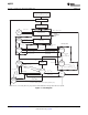
Peak Voltage (NiCd, NiMH)
The bq2000 uses a peak-voltage detection (PVD) scheme to terminate fast charge for NiCd and NiMH batteries.
The bq2000 continuously monitors the voltage on the BAT pin, representing the battery voltage, to ensure that it
never exceeds V
MCV
(maximum cell voltage). In addition, it also samples, at a rate of MTO/128, the voltage on
the BAT pin and triggers the peak detection feature if this value falls below the maximum sampled value by as
much as 3.8mV (PVD). In preparation for sampling the BAT pin voltage, the bq2000 briefly turns off most circuits
(the MOD and RC pins will both go low) in order to get the cleanest possible, noise-free measurement. While the
monitoring of the BAT pin voltage is continuous, the sampling of the BAT pin voltage with the internal ADC only
occurs during the constant current regulation phase of fast charge. If the cell voltage reaches V
MCV
, the pack is
assumed to be Li-Ion and the BAT pin voltage sampling is disabled, as PVD is not a termination criterion for
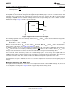
Lithium cells. As shown in Figure 3, a resistor voltage-divider between the battery pack's positive terminal and
V
SS
scales the battery voltage measured at the BAT pin.
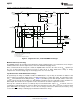
For Li-Ion battery packs, the resistor values R
B1
and R
B2
are calculated by the following equation:
(3)
where N is the number of cells in series and V
CELL
is the manufacturer-specified charging voltage. R
B1
+ R
B2
should be at least 200kΩ and no more than 1MΩ.
A NiCd or NiMH battery pack consisting of N series cells may benefit by the selection of the R
B1
value to be N–1
times larger than the R
B2
value. This sets the per cell regulation voltage (V
CELL
) equal to V
MCV
. It is critical that
V
CELL
be set high enough that the nickle pack not reach voltage regulation, thus allowing proper termination by
PVD. Typical V
CELL
for a nickle pack is between 1.7V and 2V.
In a mixed-chemistry design, a common voltage-divider is used as long as the maximum charge voltage of the
nickel-based pack is below that of the Li-Ion pack. Otherwise, different scaling is required. See Figure 7 for an
example.
Copyright © 2008–2009, Texas Instruments Incorporated Submit Documentation Feedback 9
Product Folder Link(s): bq2000